Laser-ignition unit

A laser ignition and laser technology, applied in the direction of engine ignition, spark ignition controller, engine components, etc., can solve the problems of high laser power, heating, etc.

Inactive Publication Date: 2009-06-24
GE JENBACHER
View PDF2 Cites 20 Cited by
  • Summary
  • Abstract
  • Description
  • Claims
  • Application Information

AI Technical Summary

Problems solved by technology

[0012] The disadvantages of the last known prior art are manifested in the fact that the input optics heat up strongly during operation due to the high laser power

Method used


Image

  • Laser-ignition unit
  • Laser-ignition unit
  • Laser-ignition unit

Examples


Embodiment Construction

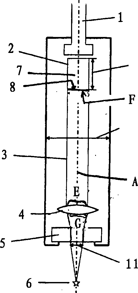
[0033] figure 1 A schematic diagram of a laser ignition device 10 according to the prior art is shown. The laser ignition device 10 is designed as a laser spark plug and comprises an ignition laser cell 2 which has a resonator 7 and an output mirror 8, so that the laser light is guided schematically via the beam path of the laser light 3 onto the input optics 8, The input optics focus the laser light 3 onto a focal point 6 where a plasma spark is generated. The laser exit surface is denoted by F and describes the surface from which the laser light of the laser generating device 2 exits before the ignitable laser light is guided onto the input optics 4 . The laser ignition device 10 is delimited by a combustion chamber window 5 through which the laser light 3 is fed into the combustion chamber 11 of the internal combustion engine 11 . The ignition laser cell 2 is supplied with pumping light by an optical waveguide 1 which is connected to a pumping light source not shown. Aft...


PUM


Abstract

The present invention relates to a laser ignition apparatus (10), including at least two laser light generating devices (2', 2'') and a common optical coupling-in means (4) for coupling laser light (3', 3'') from the at least two laser light generating devices into a combustion chamber (11) of a combustion machine, wherein the at least two laser light generating devices are so arranged that laser light given off by the laser light generating devices in the operating condition impinges on the optical coupling-in means and/or issues from the optical coupling-in means (4) in parallel displaced relationship or at an angle to each other. There are provided laser light steering elements between the laser light generating devices and the optical coupling-in means, at least two laser light generating devices are so arranged that the ejection surface of the laser light of the first laser light generating device and the ejection surface of the laser light of the second laser light generating device are arranged at an angle different from 0. The present invention also relate to a method of igniting a fuel/air mixture in a combustion chamber of a combustion machine.

Description

technical field [0001] The invention relates to a laser ignition device comprising at least two laser generating devices and a common input optics for feeding the laser light of the at least two laser generating devices into a combustion chamber of an internal combustion engine. Furthermore, the invention relates to a method for igniting a fuel / air mixture in a combustion chamber of an internal combustion engine, in which laser light is fed into the combustion chamber via a common input optics. Background technique [0002] The laser ignition device comprises at least two laser generating devices and a common input optics for inputting the laser light of the at least two laser generating devices into the combustion chamber of the internal combustion engine, wherein the input optics has a An entry surface for the laser light of the laser generating device and an exit surface for the laser light. [0003] Laser ignition is an ignition concept for gasoline-operated internal co...

Claims


Application Information

Patent Timeline
Patent Type & Authority Applications(China)
IPC IPC(8): F02P23/04
CPCF02P23/04F02P15/08
Inventor F·格鲁贝尔
Owner GE JENBACHER
Why Eureka
Try Eureka