Liquid level detection type self-calibration high-precision water gauge

A technology of liquid level detection and water level gauge, which is applied in the direction of liquid level indicator, liquid/fluid solid measurement, measuring device, etc. It can solve the problems of weight change of heavy hammer, inability to follow up, manual correction, etc., and achieve high precision and large range Measuring, avoiding cumulative errors, and realizing the effect of automatic error correction

Active Publication Date: 2009-06-24
GUANGZHOU SUNTRANS MEASUREMENT & CONTROL SYST
View PDF0 Cites 35 Cited by
  • Summary
  • Abstract
  • Description
  • Claims
  • Application Information

AI Technical Summary

Problems solved by technology

[0003] 1. Due to the long-term reciprocating movement, there is an accumulated error caused by the slipping of the steel wire rope. According to a large number of practice proofs, the accumulated error makes the water level gauge need regular manual calibration of the reference point
Otherwise, the error will become larger and larger
[0004] 2. When any encoder performs forward rotation and reverse rotation, no matter whether it is a photoelectric or mechanical encoder, there will be a pulse loss gap or error between the forward and reverse, and its cumulative error cannot meet the long-term accurate and stable measurement. Therefore, the The nominal accuracy of the type sensor is usually 0.1% within 10 meters and 0.3% above 10 meters, which cannot meet the long-term stable measurement of hydrology and hydrological forecastin

Method used


Image

  • Liquid level detection type self-calibration high-precision water gauge
  • Liquid level detection type self-calibration high-precision water gauge
  • Liquid level detection type self-calibration high-precision water gauge

Examples


Embodiment Construction

[0025] The structural details of the embodiments of the present invention are described in detail below in conjunction with the accompanying drawings:

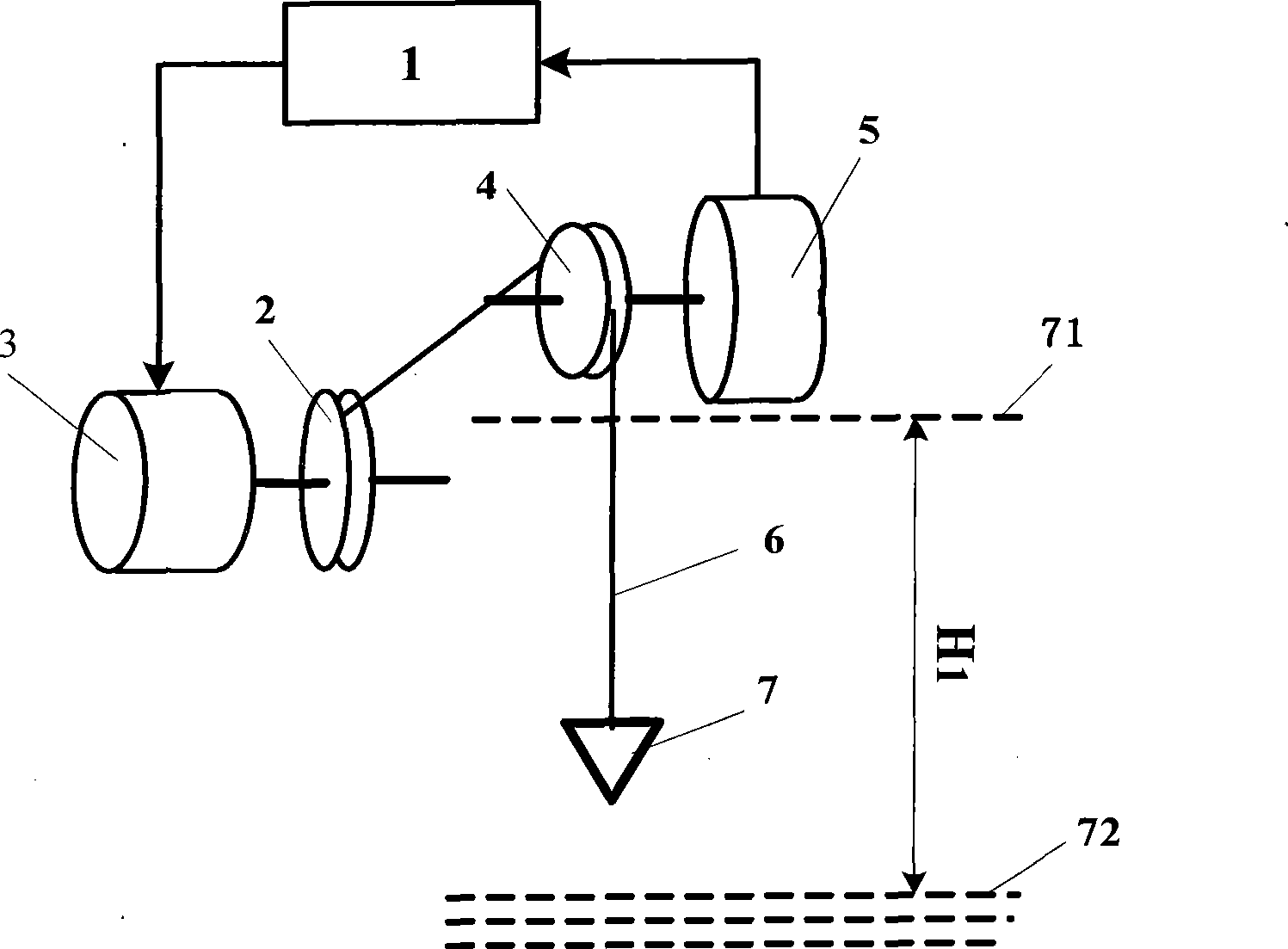
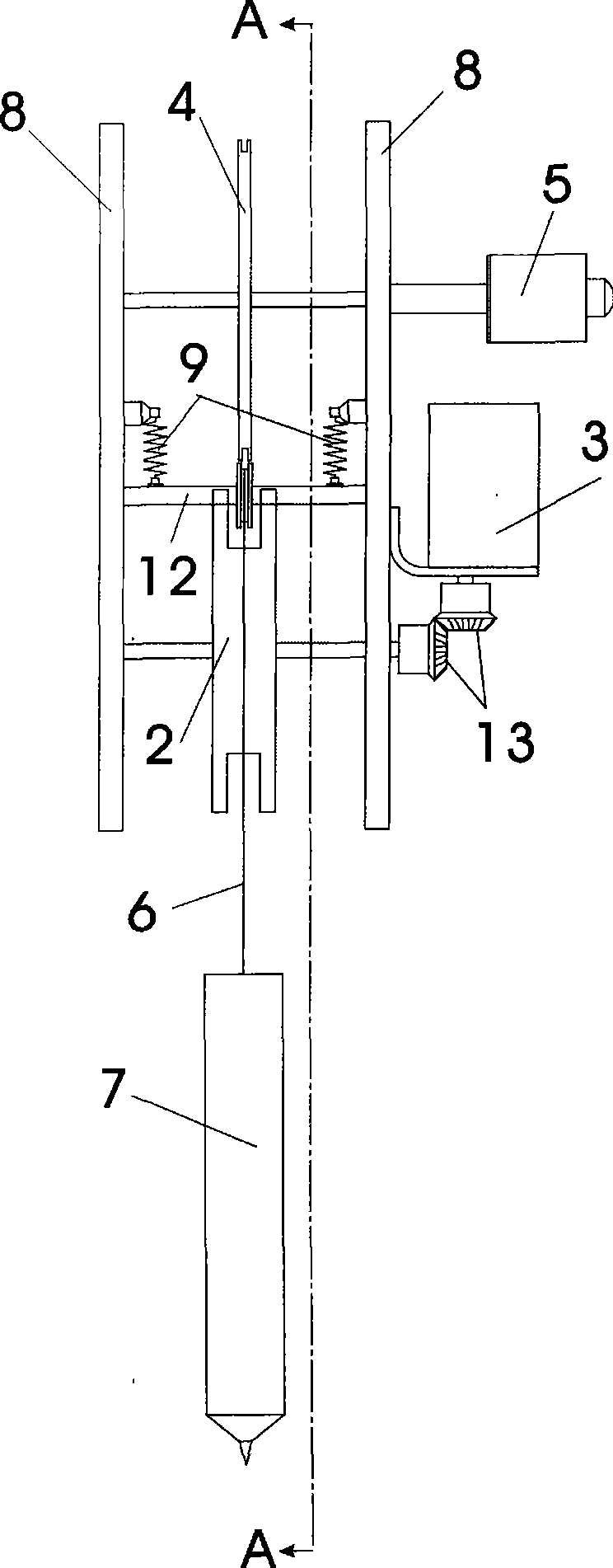
[0026] like figure 1 As shown, the present invention includes a controller 1, a wire take-up reel 2, a motor 3 that drives the wire reel 2 to rotate, a measurement transmission wheel 4, a rotary encoder 5, a steel wire rope 6 and a weight 7, and the rotating shaft of the motor 3 is connected to the steel wire The rotating shaft of take-up reel 2, steel wire rope 6 one ends are coiled on the steel wire take-up reel 2, and the other end connects weight 7 through measuring driving wheel 4, and the rotating shaft of rotary encoder 5 is connected with the rotating shaft of measuring driving wheel 4. The controller 1 issues a motor drive command to drive the motor 3 to rotate, and the motor 3 drives the steel wire take-up wheel 2 to rotate, thereby retracting the steel wire rope 6. Under the action of the weight 7, the steel wire ro...


PUM


Abstract

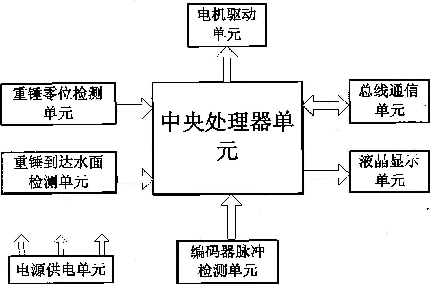
A liquid level detection-type self-calibration high-precision water level gauge comprises a controller, a steel wire take-up pulley, a motor, a measurement driving wheel, a rotary encoder, a steel wire rope and a heavy hammer. A rotating shaft of the motor is connected with a rotating shaft of the steel wire take-up pulley; the steel wire take-up pulley is wound with one end of the steel wire rope, and the other end is connected with the heavy hammer through the measurement driving wheel; the rotary encoder is connected with a measurement driving wheel shaft; the controller includes a central processing unit which outputs a motor control signal to a motor driving unit to drive the motor to rotate; a zero position detection signal of a heavy hammer zero position detection unit, a water surface detection signal of the heavy hammer arriving at a water surface detection unit, and an encoding impulse signal of an encoder impulse detection unit are input to the central processing unit; and the data is processed by the central processing unit which also transfers the data to an external data processing unit. By adopting the active liquid level detection method and the zero position self-calibration method, the invention can prevent the heavy hammer from dropping into the water, and eliminate the accumulated error produced by the skidding of the steel wire rope and the impulse loss of the encoder, thereby ensuring high-precision and wide-range measurement of the water level.

Description

Technical field: [0001] The invention relates to a liquid level detection type self-calibrating high-precision water level gauge, which can measure the water levels of reservoirs, rivers and lakes with high precision and a large range in the information system of water conservancy and water regime monitoring and reporting. Background technique: [0002] The currently widely used coded water level gauge is a passive detection water level gauge. This kind of water level gauge works by suspending the float and the weight with steel wire ropes on both sides of the measuring drive wheel. When the water level changes, the float rises and falls with the water level. As for lifting, under the action of the weight, the steel wire rope drives the measuring transmission wheel to rotate, and the rotation of the measuring transmission wheel drives the rotation of the encoder coaxially connected with it, and the rotation of the encoder will output different numbers of pulses corresponding ...

Claims


Application Information

Patent Timeline
IPC IPC(8): G01F23/00
Inventor 郑贵林
Owner GUANGZHOU SUNTRANS MEASUREMENT & CONTROL SYST
Why Eureka
Try Eureka