Varifocal full-polarization spectrum imaging detection system

A detection system and spectral imaging technology, applied in polarization spectroscopy, spectrum investigation, etc., can solve the problem of insufficient polarization detection accuracy, and achieve the effect of short response time

Inactive Publication Date: 2009-06-24
BEIHANG UNIV
View PDF0 Cites 39 Cited by
  • Summary
  • Abstract
  • Description
  • Claims
  • Application Information

AI Technical Summary

Problems solved by technology

[0004] It can be seen from researches at home and abroad that the main problems of the current polarization imaging detection optical system are: they are all fixed-focus systems, and can only achieve a certain spatial resolution at

Method used


Image

  • Varifocal full-polarization spectrum imaging detection system
  • Varifocal full-polarization spectrum imaging detection system
  • Varifocal full-polarization spectrum imaging detection system

Examples


Embodiment Construction

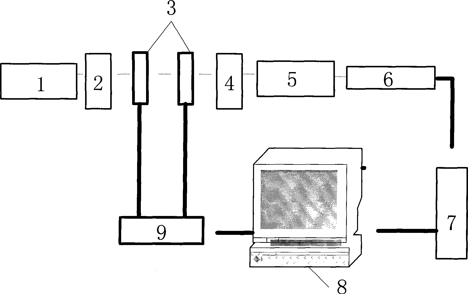
[0033] Such as figure 1 Shown, the present invention comprises zoom optical lens 1, filter plate 2, two LCVRs, polarizer 4, macro-distance optical lens 5, CCD6, electronic driver 9, image acquisition card 7 and computer 8, the image signal of CCD6 output It is sent to the computer 8 through the image acquisition card 7, the electronic driver 9 is connected to the serial port of the computer 8, and the rotating filter wheel can change the wavelength passing through the detection system to obtain the image of the target at this wavelength. The polarization measurement component consists of two LCVRs and precise polarization The polarizing axis direction of the precise polarizer is adjusted to allow only a fixed direction of polarized light to pass through, and the voltage value applied to the LCVR is controlled by the computer to change the phase delay value of the LCVR. Set 4 sets of LCVR phase delay values, respectively Collect the image, get 4 image intensity values, get a li...


PUM


Abstract

A zoom full-polarization spectral imaging detection system consists of a zoom optical lens, a spectral filter, two liquid crystal variable retarders (an LCVR1 and an LCVR2), a polarizer, a microspur optical lens, a charge-coupled device, an electronic driver, an image acquisition card and a computer. The imaging system of the system adopts a zoom optical system; the corresponding spectral imaging is achieved through the selection of suitable spectral filers; as the phase delay is changed by controlling the value of voltage applied to the two LCVRs, the full-polarization imaging of the system is realized; and the image signal of the target to be detected is collected by the computer and is subjected to image processing. The invention has the ability of subjecting a target to be detected to full-polarization spectrum detection within the range of visible wavelength or near infrared wavelength, and can achieve varying spatial resolutions in the same detection distance.

Description

technical field [0001] The invention relates to a full polarization spectrum imaging detection system with variable focal length, in particular to an optical system for space-borne, airborne and ground-to-ground full polarization spectrum imaging detection. Background technique [0002] Polarization spectrum imaging detection can provide information about the target's surface roughness, texture orientation, surface orientation, surface conductivity, physical and chemical properties of materials, water content, etc. It is used in cloud and atmospheric aerosol detection, geological exploration, soil analysis, and environmental monitoring , resource investigation, disaster estimation, agriculture, forestry and animal husbandry development, material analysis, marine development and utilization, and medical diagnosis have broad application prospects and economic value. With the development of polarization spectral imaging detection technology, the development of efficient and rel...

Claims


Application Information

Patent Timeline
IPC IPC(8): G01J3/447
Inventor 赵慧洁张颖赵海博李旭东程宣周鹏威
Owner BEIHANG UNIV
Why Eureka
Try Eureka