PM trapper failure detection system

A fault detection, trap technology, applied in membrane filters, machines/engines, chemical instruments and methods, etc., can solve problems such as difficult PM traps

Inactive Publication Date: 2009-06-24
TOYOTA JIDOSHA KK
View PDF5 Cites 15 Cited by
  • Summary
  • Abstract
  • Description
  • Claims
  • Application Information

AI Technical Summary

Problems solved by technology

Therefore, when the differential pressure between the front and rear of the PM trap changes, it is difficult to distinguish whether it is caused by a failure of the PM trap or a change in the amount of PM accumulation, and it is sometimes difficult to detect PM with high accuracy. trap failure

Method used


Image

  • PM trapper failure detection system
  • PM trapper failure detection system
  • PM trapper failure detection system

Examples


Embodiment 1

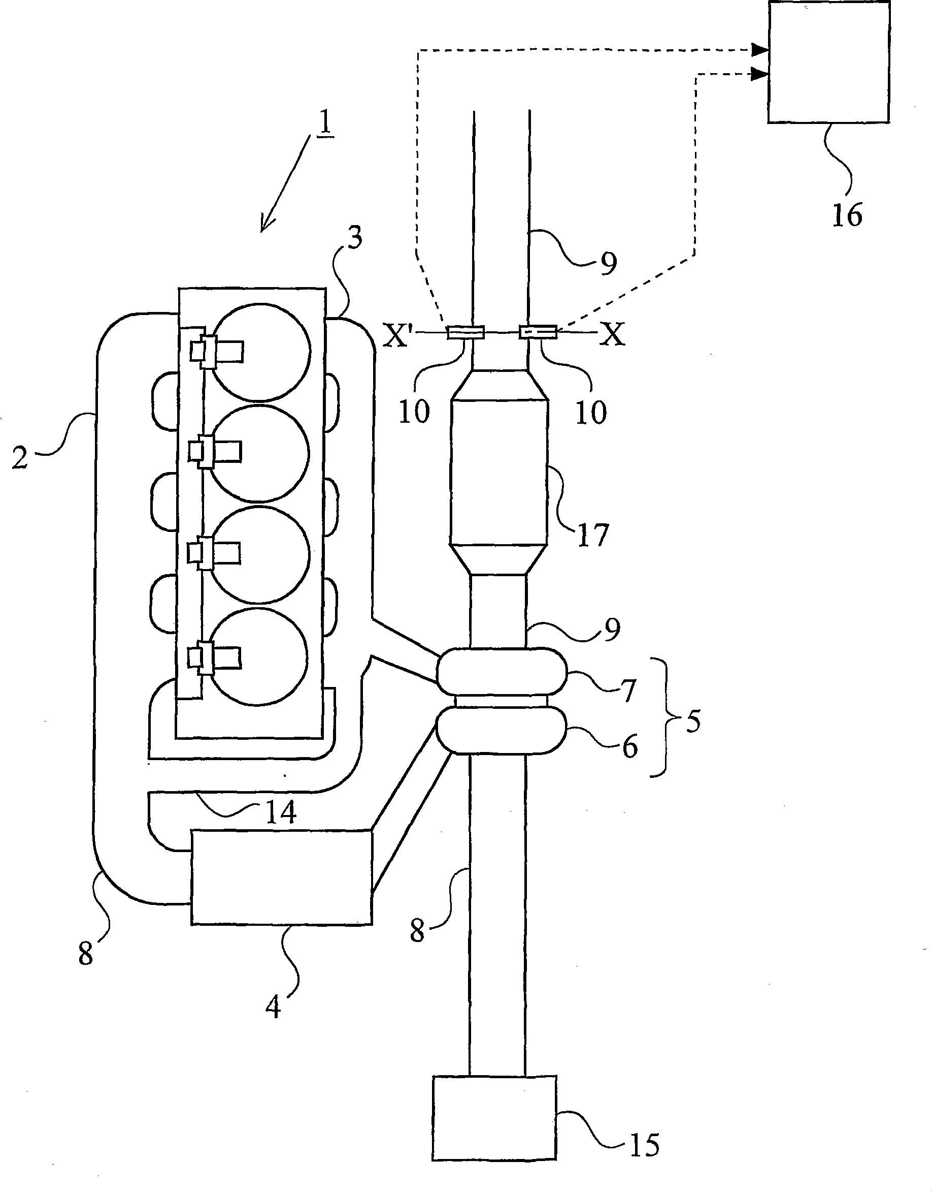
[0063] figure 1 It is a diagram showing a schematic configuration of an intake system and an exhaust system of an internal combustion engine to which the PM trap failure detection system of the present invention is applied.

[0064] figure 1 The internal combustion engine 1 shown is a water-cooled four-stroke diesel engine with four cylinders.

[0065] On the internal combustion engine 1, an intake manifold 2 is connected, and each branch pipe of the intake manifold 2 communicates with the combustion chamber of each cylinder through the intake port. An intake passage 8 is connected to the intake manifold 2 . An intercooler 4 that performs heat exchange between intake air and outside air is provided in the middle of the intake passage 8 . Upstream of the intercooler 4 is provided a compressor housing 6 of a turbocharger 5 that operates using exhaust gas energy as a drive source. Upstream of the compressor housing 6, an air filter 15 is provided.

[0066] An exhaust manifol...


PUM


Abstract

An object of the present invention is to provide a technology that enables to detect a fault of a PM trapper with improved accuracy. According to the present invention, a plurality of temperature sensors 10 are provided in an exhaust passage 9 just downstream of a PM trapper 17 in such a way that their temperature detection elements are positioned on a plane that is perpendicular to an imaginary center axis of the exhaust passage 9. A change in the radial direction temperature distribution of the exhaust gas flowing out of the PM trapper 17 upon occurrence of a fault in the PM trapper 17 is detected from measurement values of the temperature sensors 10, and a fault of the PM trapper 17 is detected based on this radial direction temperature distribution. Since the measurement values of the temperature sensors 10 are unlikely to be affected by the amount of PM deposited on the PM trapper 17, detection of a fault of the PM trapper 17 can be achieved with improved accuracy.

Description

technical field [0001] The present invention relates to a fault detection system for PM traps. Background technique [0002] In an exhaust gas purification system equipped with a PM trap for trapping particulate matter (Particulate Matter, hereinafter referred to as PM) in the exhaust gas of an internal combustion engine, it has been proposed to detect a failure of the PM trap at an early stage. technology. [0003] For example, Japanese Patent Application Laid-Open No. 6-323127 discloses a technique of comparing the minimum pressure difference between the front and rear of the PM trap immediately after the regeneration process and the new PM trap. , to detect a malfunction of the PM trap based on the comparison result. [0004] In addition, Japanese Patent Application Laid-Open No. 2004-353606 discloses a technique for an internal combustion engine including a pre-catalyst, a particulate filter downstream thereof, and a reducing agent supply unit for supplying a reducing ...

Claims


Application Information

Patent Timeline
Patent Type & Authority Applications(China)
IPC IPC(8): F01N3/02F01N3/18B01D46/42
CPCB01D2279/30Y02T10/47F01N11/002B01D46/0086F01N2550/04F01N2560/06Y02T10/40
Inventor 柴田大介泽田裕福冈圭辅
Owner TOYOTA JIDOSHA KK
Why Eureka
Try Eureka