Supercharge Your Innovation With Domain-Expert AI Agents!

Power distribution system for integrated circuits

An integrated circuit and power technology, applied in the direction of circuits, printed circuit components, electrical components, etc., can solve difficult and expensive, high-loss dielectric problems and other problems

Inactive Publication Date: 2009-06-24
特拉速率咨询集团公司
View PDF5 Cites 3 Cited by
  • Summary
  • Abstract
  • Description
  • Claims
  • Application Information

AI Technical Summary

Problems solved by technology

[0013] 1. Fine interval filter zero;
[0014] 2. High loss dielectric;
[0015] 3. High skin loss interconnection;
Building such a distribution system becomes difficult and expensive, if not impossible, as device performance increases in frequency and power

Method used


Image

  • Power distribution system for integrated circuits
  • Power distribution system for integrated circuits
  • Power distribution system for integrated circuits

Examples


Embodiment Construction

[0129] Techniques for Optimizing Power Distribution Systems

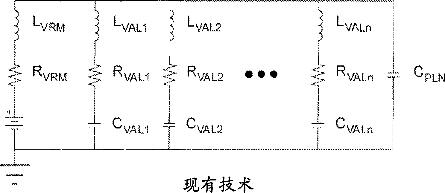
[0130] Such as Figure 12 As shown in the power distribution system 100 of , these power and ground plane 111 pairs of PCB 110 can be paired together to take advantage of mutual inductance and inter-plane capacitance. These mutual inductances of the power and ground planes 111 of the PCB 110 reduce the inductance of the power distribution paths as a whole. Reducing the inductance of the power distribution path increases the power distribution bandwidth. These interplane capacitances of the power and ground planes 111 of the PCB 110 provide a small amount of energy storage, but interact with other parallel inductances within the power distribution system 100 . This point is a key parameter at high frequencies.

[0131] Capacitors 112 on PCB 110 provide energy storage within power distribution system 100 . Capacitors 112, 122, and 132 may be mounted on a substrate, which includes PCB 110, interposer 120, and IC pa...


PUM


Abstract

Power distribution system for integrated circuits includes methods to damp resonance between a bypass capacitor network and a power / ground cavity of the printed circuit board that (a) does not require excessive quantities of bypass / damping components or (b) does not require high plane cavity capacitance or in the alternative can insure a Q of less than 1.4 at the transition from the bypass network to the plane cavity impedance cross-over.

Description

technical field [0001] The present invention relates to power distribution for integrated circuits (ICs). More specifically, the present invention relates to power distribution for ICs connected to printed circuit boards (PCBs). Background technique [0002] In recent years, high-speed operating circuit devices have been required, and research has been conducted on them. A circuit device capable of high-speed operation will realize a drastic reduction in processing time that previously took a long time, allow processing previously thought to be impossible, and will make it possible to perform a large number of tasks using one device instead of a plurality of devices, thereby reducing Small processing costs and contribute to the development of services, facilities, functions, etc. [0003] The supply voltage to a circuit should not vary substantially over time. Even if the current consumption of the circuit does not fluctuate substantially over a short period of time, the ...

Claims


Application Information

Patent Timeline
IPC IPC(8): H05K1/11
CPCH01L2924/19105H01L2924/3011H01L2224/16225
Inventor 史帝夫·威耳史考特·麦克莫若
Owner 特拉速率咨询集团公司
Features
  • R&D
  • Intellectual Property
  • Life Sciences
  • Materials
  • Tech Scout
  • Unparalleled Data Quality
  • Higher Quality Content
  • 60% Fewer Hallucinations
Learn More