Fuel injection control device for engine

A technology of fuel injection and control device, which is applied in the direction of fuel injection device, fuel injection control, engine control, etc., and can solve problems such as being unable to be a solution.

Inactive Publication Date: 2009-07-01
MITSUBISHI FUSO TRUCK AND BUS CORPORATION
View PDF1 Cites 3 Cited by
  • Summary
  • Abstract
  • Description
  • Claims
  • Application Information

AI Technical Summary

Problems solved by technology

However, the technology of Patent Document 1 is not aimed at preventing the formation of a fuel-rich region in the cylinder.
Therefore, the technology of Patent Document 1 cannot be a solution to the above-mentioned problem, and effective measures for solving the above-mentioned problem have been desired all the time.

Method used


Image

  • Fuel injection control device for engine
  • Fuel injection control device for engine

Examples


Embodiment Construction

[0026] Next, a fuel injection control device for an engine according to an embodiment of the present invention will be described with reference to the drawings.

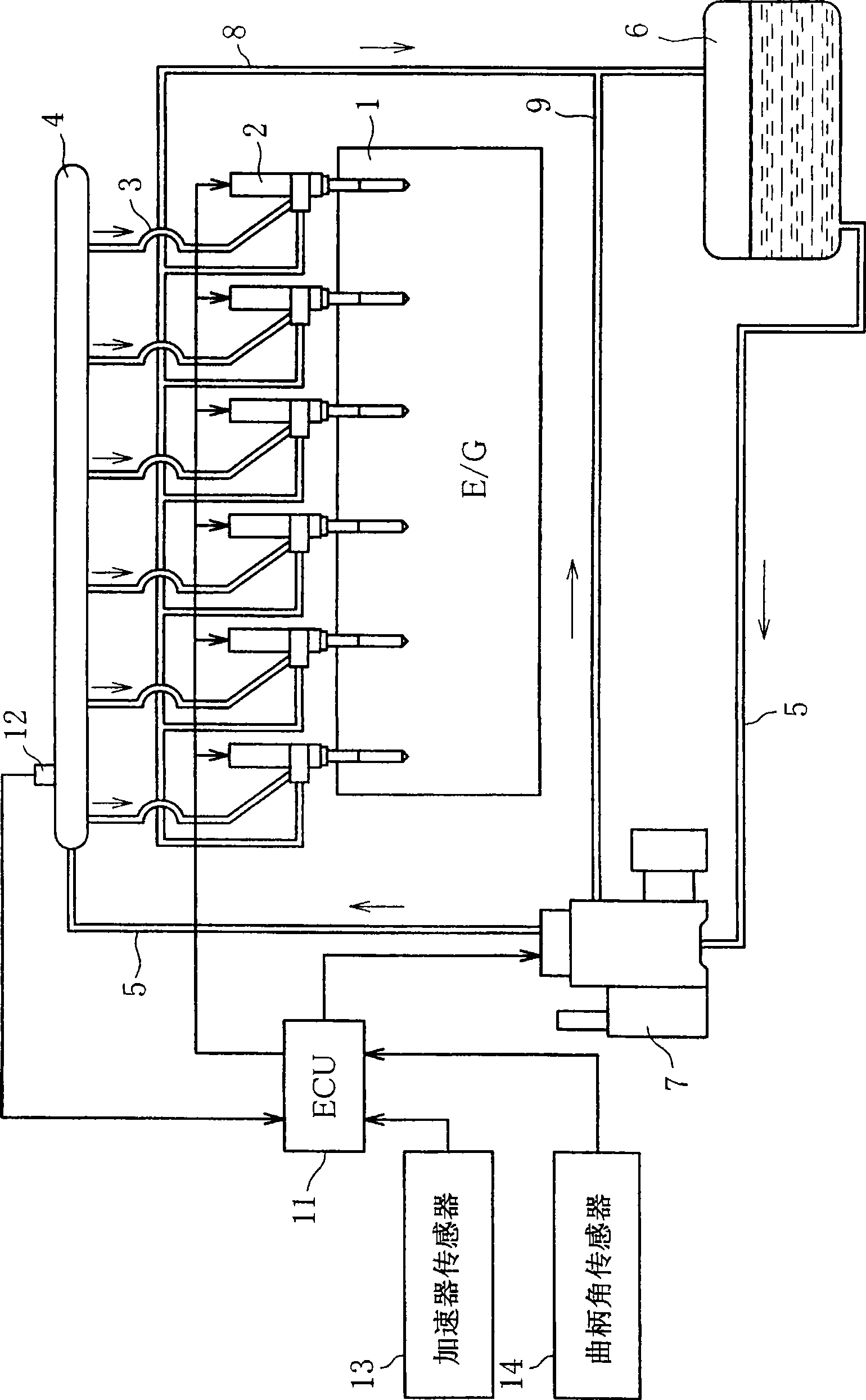
[0027] figure 1 is an overall configuration diagram showing a fuel injection control device for an engine according to the present embodiment. In the present embodiment, the engine 1 is configured as an in-line 6-cylinder diesel engine mounted on a vehicle. A fuel injection valve (fuel injection unit) 2 is provided on each cylinder of the engine 1 .

[0028] Each fuel injection valve 2 is connected to a common fuel rail (fuel supply unit) 4 via a fuel distribution line 3 . The common fuel rail 4 is connected to a fuel tank 6 of the vehicle via a fuel pressure feed line 5 . In the fuel pressure-feeding line 5, a supply pump 7 constituted by a positive displacement plunger pump is provided. As is well known, the charge pump 7 is driven in synchronization with the rotation of the engine 1, pressurizes the fuel from...


PUM


Abstract

The invention provides a fuel injection control device for an engine. In the main injection process, an ECU (11) reduces the lift capacity of the pin valve of a fuel injection valve and temporarily reduces the fuel injection rate, thereby temporarily reducing the fuel supply in an air cylinder, promoting the combustion of the surplus fuel in the flue over-rich region and decreasing the flue over-rich region. Then, the ECU (11) increases the fuel injection rate again by increasing the lift capacity of the pin valve, thereby maintaining favorable combustion state.

Description

technical field [0001] This Act relates to a fuel injection control device for an engine, and more specifically, relates to a fuel injection control device capable of changing a fuel injection rate when fuel is injected into a cylinder. Background technique [0002] For example, a diesel engine operates with diffusion combustion as the main combustion method, where combustion occurs in a combustible mixture layer formed at the interface between the injected fuel and the surrounding compressed air. In such an engine, the valve opening period and valve opening start timing of the fuel injection valve are determined based on the accelerator pedal operation amount, engine rotation speed, etc., and the fuel injection valve is controlled based on the valve opening period and valve opening start timing. [0003] The control of the fuel injection valve and the combustion in the cylinder by such a conventional fuel injection control device, for example, in figure 2 is executed as sh...

Claims


Application Information

Patent Timeline
Patent Type & Authority Applications(China)
IPC IPC(8): F02D41/38
CPCF02D41/40Y02T10/44F02M63/0225F02M45/02Y02T10/40
Inventor 松本祐介椎野始郎山田阳春奥出圭一
Owner MITSUBISHI FUSO TRUCK AND BUS CORPORATION
Why Eureka
Try Eureka