Method for measuring positive pressure leak hole leak rate

A positive pressure leak, measurement method technology, applied in the direction of measuring the acceleration and deceleration rate of fluid, using liquid/vacuum for liquid tightness measurement, etc., can solve the problem of long measurement time, measurement uncertainty, large uncertainty, etc. problems, to achieve the effect of small measurement uncertainty, improve work efficiency, and improve accuracy

Inactive Publication Date: 2009-07-01
NO 510 INST THE FIFTH RES INST OFCHINA AEROSPAE SCI & TECH
View PDF0 Cites 15 Cited by
  • Summary
  • Abstract
  • Description
  • Claims
  • Application Information

AI Technical Summary

Problems solved by technology

[0003] The disadvantage of this method is that the lower limit of measurement cannot reach 5×10 -6 Pa·m 3 / s and below, and the uncertainty of the measurement results is large, and the measurement time is long. The main reason is that this method measures the leak rate of the positive pressure leak by measuring the pressure rise of the constant volume chamber. The leak rate is less than 5×10 -6 Pa·m 3 / s, it takes 1 hour or more to accumulate the pressure, and during this period, the pressure fluctuation caused by the temperature change will have a great impact on the leak rate measurement results; and after the constant volume chamber pressure rises, it cannot Satisfy the measurement condition that the outlet port of the positive pressure leak is 1 atmosphere, and there will be a measurement uncertainty component

Method used


Image

  • Method for measuring positive pressure leak hole leak rate
  • Method for measuring positive pressure leak hole leak rate
  • Method for measuring positive pressure leak hole leak rate

Examples


Embodiment Construction

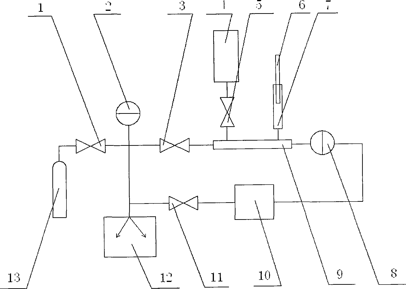
[0029] Such as figure 1 Shown, the measuring device of the leak rate of positive pressure leak that the present invention adopts is by vacuum valve 1,3,5,11, absolute pressure gauge 2, positive pressure leak 4, piston 6, variable capacity chamber 7, differential pressure type A pressure gauge 8, a variable volume chamber main body 9, a standard container 10, a vacuum pump 12, and a gas cylinder 13 are formed.

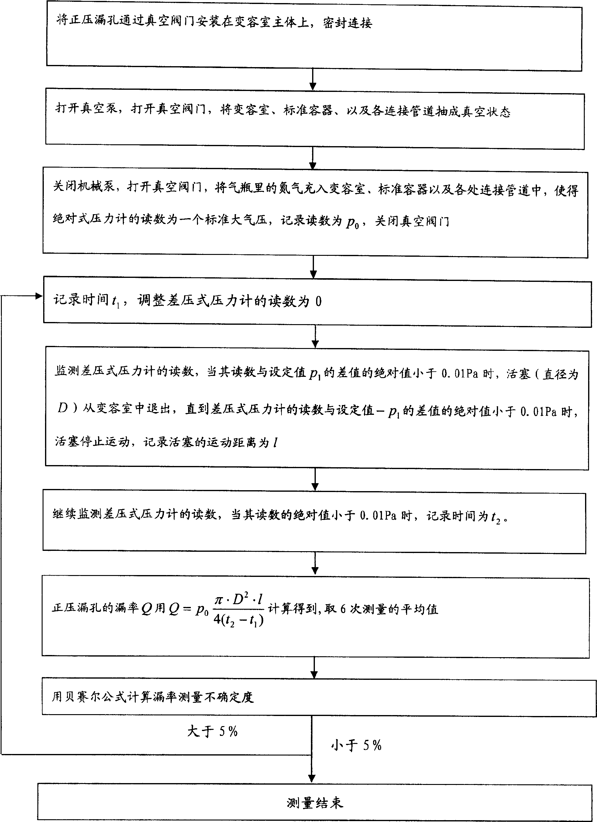
[0030] The specific steps are:

[0031] (1) Install the positive pressure leakage hole 4 on the main body 9 of the variable volume chamber through the vacuum valve 5 .

[0032] (2) Open the vacuum pump 12, open the vacuum valves 3 and 11, and the variable volume chamber 7 (volume 9ml), the standard container 10 (volume 1.1×10 -3 m 3 ), and each connecting pipe is pumped into a vacuum state (vacuum degree is 0.06Pa).

[0033] (3) Close the vacuum pump 12, open the vacuum valve 1, and fill the nitrogen in the gas cylinder 13 into the variable capacity chamber 7, the s...


PUM


Abstract

The invention relates to a measurement method for the leak rate of pressure leak, belonging to the measurement technical field. A leak rate measurement device for pressure leaks adopted by the measurement method is composed of four vacuum valves 1, 3, 5, 11, an absolute pressure meter 2, a pressure leak 4, a piston 6, a volume-varied chamber 7, a pressure differential pressure meter 8, a volume-varied chamber body 9, a standard container 10, a vacuum pump 12 and a gas bottle. The measurement method utilizes the motion of the piston in the volume-varied chamber to change the capacity of the volume-varied chamber, to keep the pressures of the volume-varied chamber consistent at the start and the end of the measurement; and measures the pressure of the volume-varied chamber, the sectional area of the piston, the motion distance of the piston, and the experiment time to calculate the leak rate of the pressure leak. The pressure change curve of the volume-varied chamber is in saw tooth form. The measurement method can measure the leak rate not higher than 5x10 Pam3/s, has short measurement time, reduces the measurement uncertainty from prior 9.1% to 5%, and improves working efficiency.

Description

technical field [0001] The invention relates to a method for measuring positive pressure leak rate and belongs to the field of precision measurement. Background technique [0002] The document "Design of Positive Pressure Leak Calibration Device, "China Space Science and Technology", Vol. 21, No. 1, 2001, Pages 57-64", introduces a method for measuring the leak rate of positive pressure leaks, called For constant volume method. The method is to fill a constant volume chamber with a known volume U with air at an atmospheric pressure, introduce the leakage gas into the constant volume chamber through the positive pressure leak hole, cause the pressure change in the constant volume chamber and use a capacitance film vacuum gauge To measure, by measuring the pressure change value Δp and the elapsed time Δt in the constant volume chamber, and taking into account the temperature correction , the leak rate Q of the positive pressure leak can be calculate. The lower limit of m...

Claims


Application Information

Patent Timeline
Patent Type & Authority Applications(China)
IPC IPC(8): G01M3/32
Inventor 冯焱张涤新邱家稳李得天成永军卢耀文李正海
Owner NO 510 INST THE FIFTH RES INST OFCHINA AEROSPAE SCI & TECH
Why Eureka
Try Eureka