Overcurrent detection circuit, decompression converter and overcurrent detection method

A buck converter, overcurrent detection technology, applied in the direction of measuring current/voltage, measuring electrical variables, instruments, etc., can solve the problems of affecting the current limiting effect, the output current affecting the current limiting effect, etc., to achieve simple and easy implementation Effect

Inactive Publication Date: 2009-07-01
INVENTEC CORP
View PDF0 Cites 18 Cited by
  • Summary
  • Abstract
  • Description
  • Claims
  • Application Information

AI Technical Summary

Problems solved by technology

[0006] The purpose of the present invention is to provide an overcurrent detection circuit to solve the technical problem of using the conduction voltage drop of the lower field effect transistor to determine whether the output current is too large, which is affected by temperature changes, and then affects the current limiting effect
[0007] Another object of the present invention is to provide a step-down converter to solve the technical problem of using the conduction voltage drop of the lower f

Method used


Image

  • Overcurrent detection circuit, decompression converter and overcurrent detection method
  • Overcurrent detection circuit, decompression converter and overcurrent detection method
  • Overcurrent detection circuit, decompression converter and overcurrent detection method

Examples


Embodiment Construction

[0027] The present invention will be described in detail below in conjunction with the accompanying drawings.

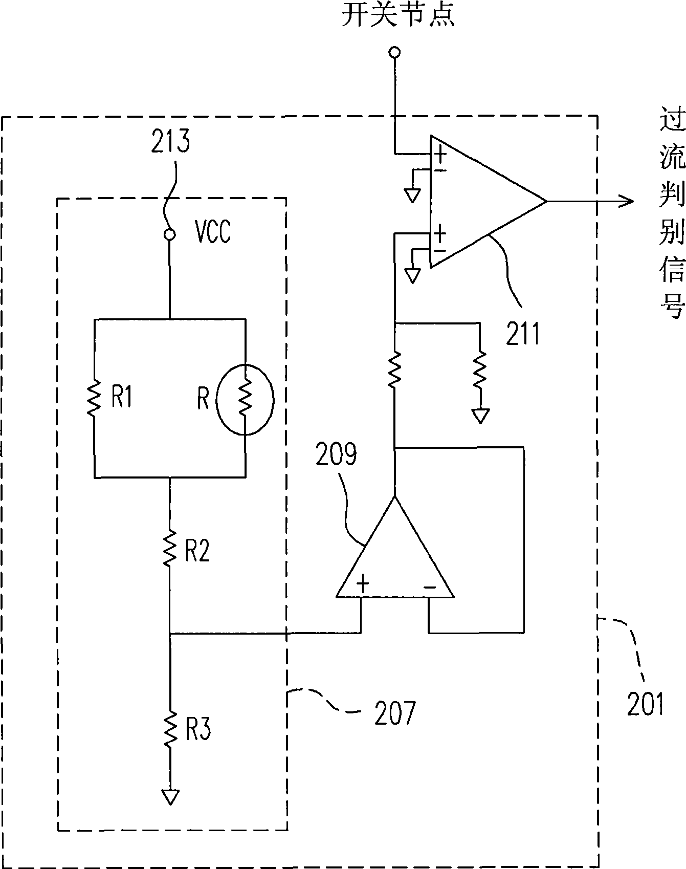
[0028] See figure 2 , which is a schematic structural diagram of an overcurrent detection circuit according to an embodiment of the present invention. The overcurrent detection circuit 201 includes a voltage generation circuit 207 , a voltage follower 209 and an operational amplifier 211 . The voltage generating circuit 207 includes a voltage input terminal 213 , a thermistor R, a first resistor R1 , a second resistor R2 and a third resistor R3 . The first resistor R1 is connected in parallel with the thermistor R and is arranged between the voltage input terminal 213 and the second resistor R2. One end of the second resistor R2 is connected in series with the parallel-connected thermistor R and the first resistor R1, and the other end is used as a reference voltage output end and connected to the third resistor R3. One end of the third resistor R3 is connected t...


PUM


Abstract

The invention provides an over current measurement circuit, which is connected with the switch node of a low order field transistor of a step down converter. The over current measurement circuit comprises a voltage generation circuit and an operational amplifier, wherein the voltage generation circuit generates a reference voltage which is automatically adjusted according to temperature change, and comprises a voltage input end and a thermal sensitive resistor; the voltage input end provides a voltage; the thermal sensitive resistor is connected with the voltage input end for generating divided voltages of the voltage input by the voltage input end; the divided voltages automatically adjust according to temperature change; the voltage input by the voltage input end forms a reference voltage after voltage division. The operational amplifier comprise two inputs, wherein one input end is connected with the voltage generation circuit and the other input end is connected with the switch node of a low core field transistor of a step down converter. The over current measurement circuit can prevent the current limit or protective value set by step down converters from being affected by temperature.

Description

technical field [0001] The invention relates to an overcurrent detection circuit and a corresponding step-down converter, in particular to an overcurrent detection circuit and a corresponding step-down converter which are not affected by temperature changes. Background technique [0002] As the power supply equipment of all electronic products, in addition to the performance that meets the requirements of power supply products, its own protection measures are also very important, such as overvoltage, overcurrent, and overheat protection. Once an electronic product fails, such as a short circuit on the input side or an open circuit on the output side of the electronic product, the power supply must turn off its output voltage to protect the internal components of the power supply and the load provided by the power supply from being burned, otherwise it may cause electronic products. Further damage, and even cause the operator's electric shock and fire. Therefore, the protect...

Claims


Application Information

Patent Timeline
IPC IPC(8): G01R19/165G01R31/40
Inventor 夏春华刘士豪
Owner INVENTEC CORP
Why Eureka
Try Eureka