
Tool-pulling structure for horizontal lathe tiger head tool holder

A technology of tiger-head tool holder broaching and horizontal lathe, which is applied in the direction of tool holders, etc., can solve the problems of increasing the auxiliary time of machine tool processing preparation, re-calibrating the origin of the tool tip, and the long time of tool clamping and loosening, etc., to achieve The effect of improving market competitiveness, saving tool setting time, and shortening tool change time

Inactive Publication Date: 2010-11-03
通用技术齐齐哈尔二机床有限责任公司
View PDF0 Cites 0 Cited by
  • Summary
  • Abstract
  • Description
  • Claims
  • Application Information

AI Technical Summary

Problems solved by technology

[0002] In the current field of mechanical processing, the tool holder of horizontal lathe generally adopts the traditional form of directly tightening the turning tool with a screw. Every time a tool is changed, it is first necessary to manually loosen the set screw to remove the tool, and then install another tool. , re-tighten the screw, and after each tool change, it is necessary to try to cut the workpiece and re-calibrate the origin of the tool tip. During the entire tool change process, the tool clamping and loosening time is long, labor-intensive, and it takes a long time to re-calibrate the origin of the tool tip , and the tool clamping and loosening time and the tool setting time are all auxiliary time for machine tool processing. Therefore, the existing structure increases the auxiliary time for machine tool processing, making the machine tool processing parts inefficient, and frequent tightening and loosening Open the screw, so that the labor intensity of the workers is high

Method used


Image

  • Tool-pulling structure for horizontal lathe tiger head tool holder
  • Tool-pulling structure for horizontal lathe tiger head tool holder
  • Tool-pulling structure for horizontal lathe tiger head tool holder

Examples


Embodiment Construction

[0011] The present invention will be further described below in conjunction with accompanying drawing:

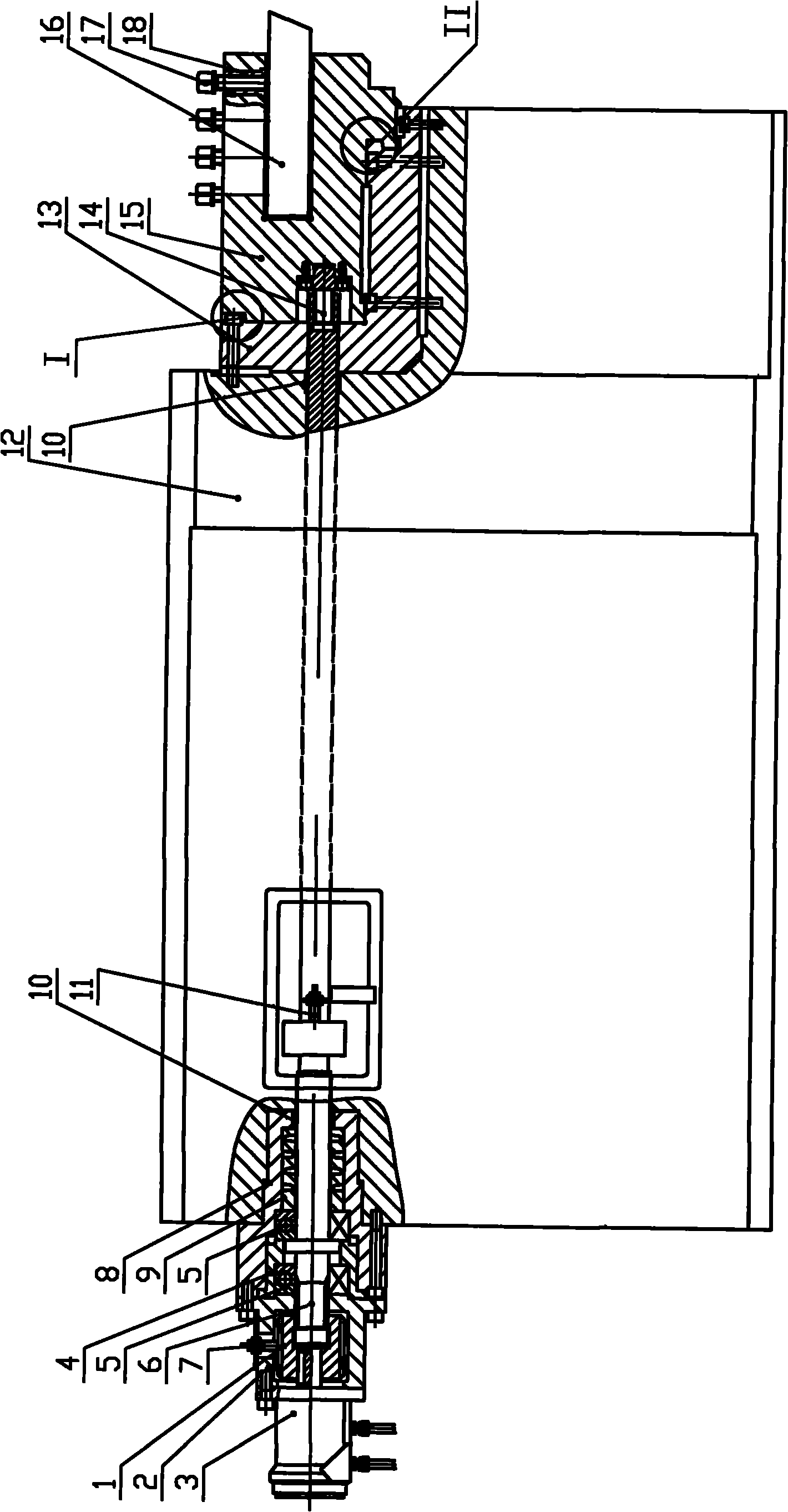
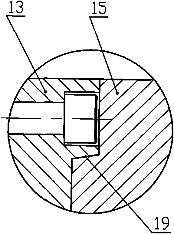
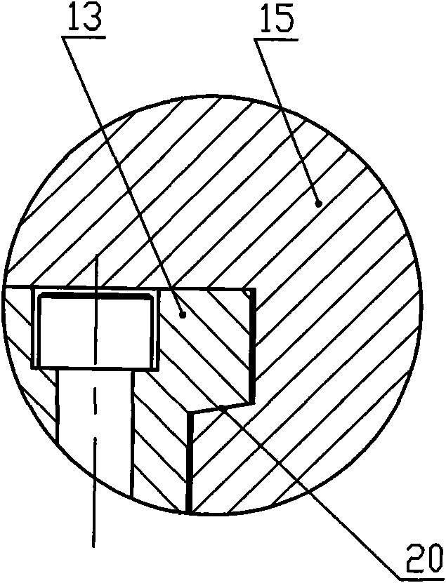
[0012] Depend on figure 1 to combine figure 2 , image 3 As shown, a horizontal lathe tiger head tool clip broaching device includes an L-shaped knife plate 12, a bearing seat 8 is embedded on the left side of the L-shaped knife plate 12, and the bearing seat 8 is fixed on the workbench 19 by screws. The interior of 8 is stepped, and there is a damping sleeve 9 inside the right side, which is set outside the lock knife pull rod 6 to play a role of vibration reduction and reduce the vibration and noise generated when the lock knife pull rod 6 rotates. The bearing seat 8 There is a flange cover 4 inside the left side, and a bearing 5 is respectively installed inside the bearing seat 8 and the flange cover 4, and the bearing 5 plays the role of supporting the lock knife pull bar 6. A locking limit switch 11 is installed on the right side of the bearing seat 8 and inside th...


PUM


Abstract

The invention relates to a horizontal lathe tiger head tool holder broach structure, which mainly solves the problem that long reblading time of the horizontal lathe increases auxiliary time of lathe processing. The invention is characterized in that a shaft block (8) with a vibration damping sheath (9) inside is arranged at the left side of a cutting board (12), wherein, a flange sheath (4) is arranged at the left side of the shaft block (8) internally. A bearing (5) supporting a lock cutter tie rod (6) is positioned inside the two (4, 8) respectively. The left side of the lock cutter tie rod (6) is connected with the output shaft of a motor (3) through a shaft joint (1), and the right side of the same is connected with a tiger head tool holder (15) by a tool holder pop-rivet (14) after passing through the cutting board (12) with L shape and the tool holder permanent seat (13). The horizontal lathe tiger head tool holder broach structure has the characteristics of short reblading time and shorter auxiliary time of lathe processing, in addition, the labor intensity of worker is lowered.

Description

Technical field: [0001] The invention belongs to the technical field of mechanical manufacturing, and in particular relates to a tiger head tool holder broaching device for a horizontal lathe. Background technique: [0002] In the current mechanical processing field, the tool holder of horizontal lathe generally adopts the traditional form of directly tightening the turning tool with a screw. Every time a tool is changed, it is first necessary to manually loosen the set screw to remove the tool, and then install another tool. , re-tighten the screw, and after each tool change, it is necessary to try to cut the workpiece and re-calibrate the origin of the tool tip. During the entire tool change process, the tool clamping and loosening time is long, labor-intensive, and it takes a long time to re-calibrate the tool tip origin , and the tool clamping and loosening time and the tool setting time are all auxiliary time for machine tool processing. Therefore, the existing structur...

Claims


Application Information

Patent Timeline
Patent Type & Authority Patents(China)
IPC IPC(8): B23B29/12
Inventor 张权尚连峰李立强程凤兰王泽民
Owner 通用技术齐齐哈尔二机床有限责任公司
Learn More