Combustion device with thin and thick breeze airflow stagger arrangement used for W-shaped flame furnace
A combustion device, the technology of rich and thin pulverized coal, which is applied in the combustion of lump fuel and gaseous fuel, the combustion of lump fuel and powder fuel, the combustion of liquid fuel and gaseous fuel, etc., can solve the problem of unstable combustion, Can not catch fire in time and other problems, to achieve the effect of increasing the residence time, improving the comprehensive index, and increasing the itinerary
- Summary
- Abstract
- Description
- Claims
- Application Information
AI Technical Summary
Problems solved by technology
Method used
Image
Examples
specific Embodiment approach 1
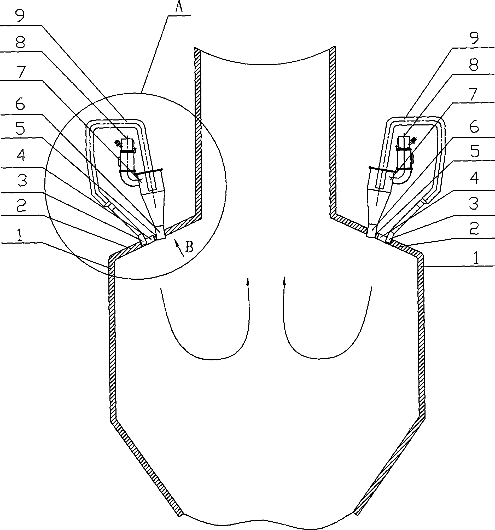
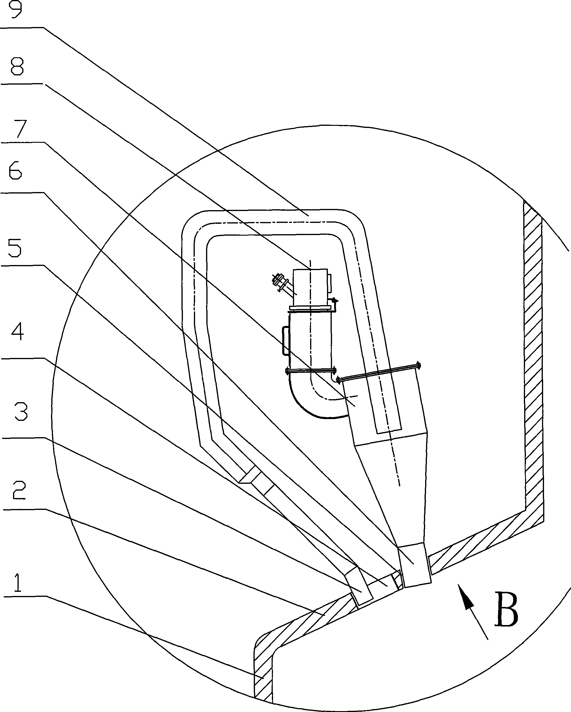
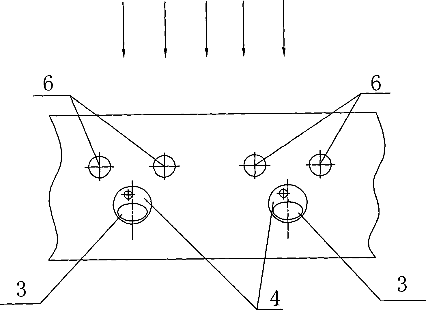
[0009] Specific implementation mode one: as Figure 1~5 As shown, the combustion device used in this embodiment for the staggered arrangement of thick and thin pulverized coal flow on the W-shaped flame furnace, the combustion device includes two cyclones 7, two pulverized coal inlet pipes 8, light pulverized coal Air flow air duct 9, two dense coal powder air flow burners 6 and light coal powder air flow burner 3; light coal powder air flow air duct 9 is made of main pipe 9-1 and two branch pipes 9-2; each cyclone 7 The side wall at the upper end communicates with a pulverized coal inlet pipe 8, one end of each branch pipe 9-2 is inserted into the upper inner cavity of a cyclone 7, and the other ends of the two branch pipes 9-2 communicate with one end of the main pipe 9-1 , the other end of the main pipe 9-1 communicates with the light coal powder flow burner 3, and the lower end of each cyclone 7 communicates with a thick coal powder flow burner 6, and the light coal powder...
specific Embodiment approach 2
[0011] Specific implementation mode two: as Figure 1~5 As shown, the cross-section of the light coal powder flow burner 3 in this embodiment is elliptical, and the vertical plane where the major axis of the ellipse is located is parallel to the front wall or the rear wall 1 . With such a design, after the light coal powder airflow enters the furnace, it will receive the radiant heat from the center of the furnace with the largest area, which is more conducive to heat absorption and ignition. Other components and connections are the same as those in the first embodiment.
specific Embodiment approach 3
[0012] Specific implementation mode three: as Figure 1~5 As shown, the cross-section of the rich pulverized coal flow burner 6 and the surrounding peripheral air nozzle 5 in this embodiment are all circular. The cross-section of the dense coal powder flow burner 6 and the peripheral air nozzle 5 on its periphery are all circular, which can make the air flow at the outlet have greater rigidity, and can further go deep into the furnace, increase the stroke, and promote the combustion of pulverized coal, thereby improving combustion efficiency. Other compositions and connections are the same as those in Embodiment 1 or 2.
[0013] working principle:
[0014] When in use, several combustion devices of the present invention are arranged on the front and rear furnace arches of the W-shaped flame furnace. The pulverized coal airflow that enters the cyclone 7 through the pulverized coal inlet pipe 8 is divided into two strands, which are injected into the furnace through the burne...
PUM
 Abstract
Description
Claims
Application Information
 - R&D
- Intellectual Property
- Life Sciences
- Materials
- Tech Scout
- Unparalleled Data Quality
- Higher Quality Content
- 60% Fewer Hallucinations
Browse by: Latest US Patents, China's latest patents, Technical Efficacy Thesaurus, Application Domain, Technology Topic, Popular Technical Reports.
© 2025 PatSnap. All rights reserved.Legal|Privacy policy|Modern Slavery Act Transparency Statement|Sitemap|About US| Contact US: help@patsnap.com


