
Surface plasma resonance sensor

A resonant sensor, surface plasma technology, applied in instruments, scientific instruments, optics, etc., can solve the problems that the sensor is not very convenient to use, not very ideal, and cannot eliminate the influence of the light intensity of the light source on the measured signal, so as to improve the detection stability. , The effect of easy adjustment and simple optical path

Inactive Publication Date: 2009-07-08
浙江诺迦生物科技有限公司
View PDF0 Cites 20 Cited by
  • Summary
  • Abstract
  • Description
  • Claims
  • Application Information

AI Technical Summary

Problems solved by technology

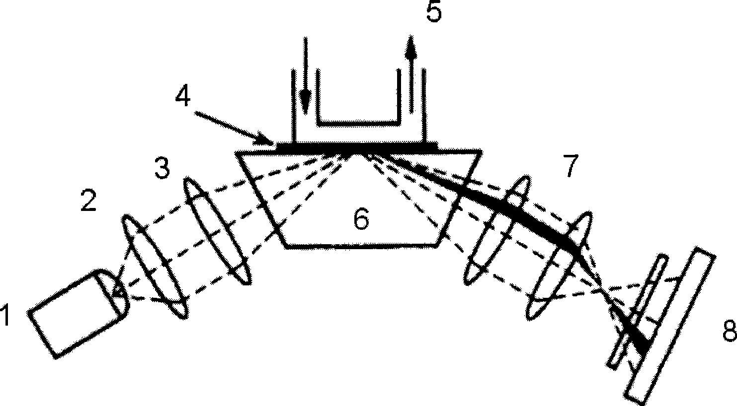
Although this method can improve the final SPR signal to a certain extent and improve the detection accuracy, since the air signal is obtained at the beginning of the measurement, the normalization process has a certain time limit, and it cannot Eliminate the influence of changes in the light intensity of the light source and environmental conditions on the measured signal during the detection process, so this method is not very ideal
At the same time, because the light intensity signal when the surface of the sensor is air must be obtained before each measurement, and the surface of the metal film must be dry and free of liquid, which makes the use of the sensor inconvenient

Method used


Image

  • Surface plasma resonance sensor
  • Surface plasma resonance sensor
  • Surface plasma resonance sensor

Examples


Embodiment Construction

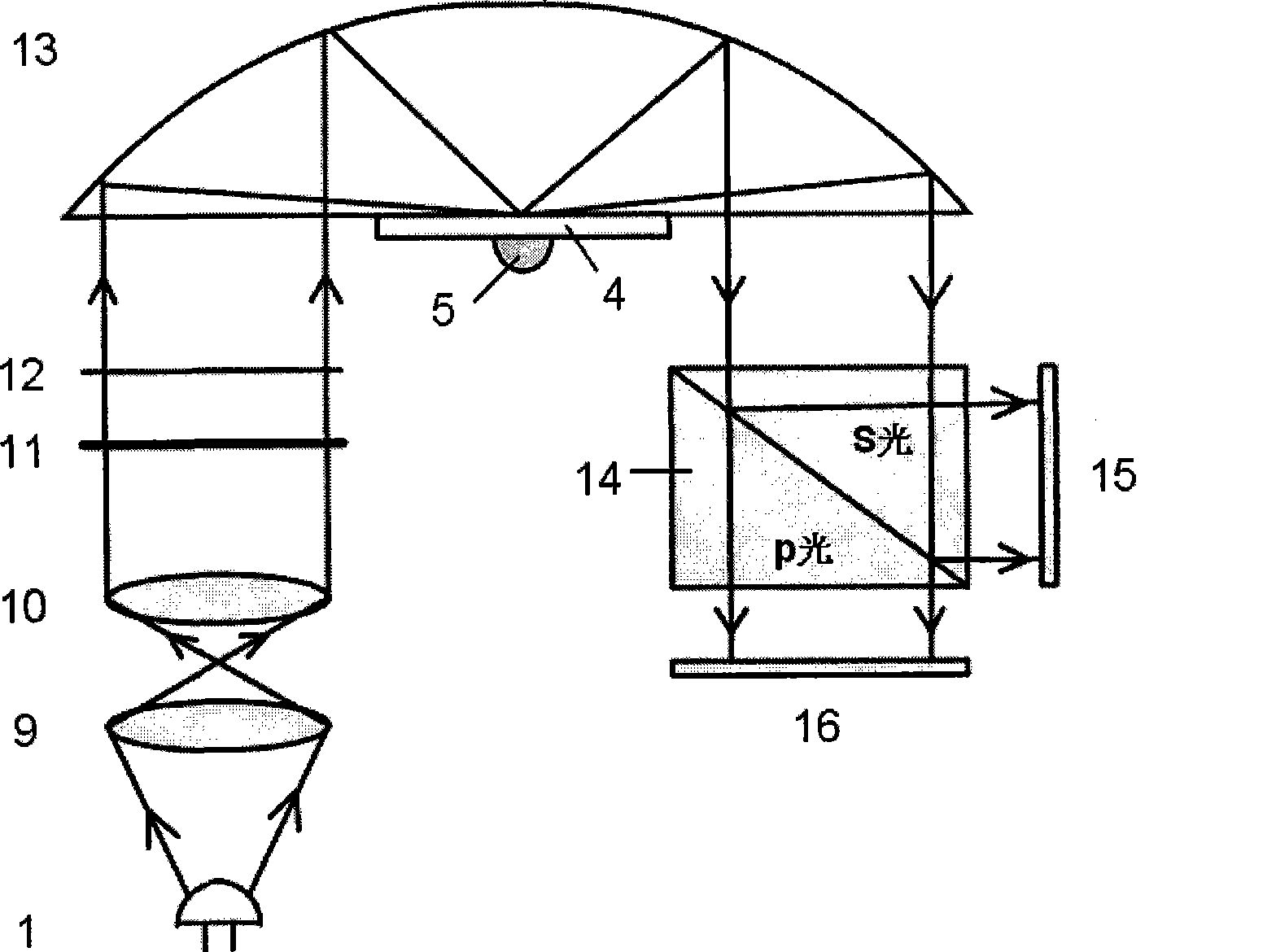
[0021] Such as figure 2 As shown, the surface plasmon resonance sensor of the present invention includes a light-emitting component, a light-receiving component, and a light-reflecting component for receiving light emitted by the light-emitting component and reflecting it to the light-receiving component:

[0022] The light emitting component is sequentially provided with a light source 1, a beam expander 9, a collimator 10, a filter 11 and a rectangular diaphragm 12 along the light direction;

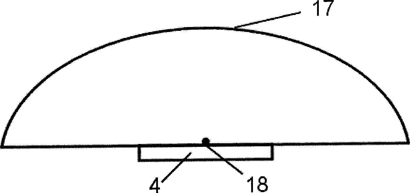
[0023] The light reflection assembly is composed of a parabolic reflective prism 13 and a metal thin film 4 located at the focal line 18 of the parabolic reflective prism 13, wherein the metal thin film 4 is used to flow through the measured liquid on the side facing away from the parabolic reflective prism 13 5;

[0024] The light receiving assembly consists of a polarizing beamsplitter prism 14 that receives the light emitted by the light reflecting assembly, a first CCD array 15 f...


PUM


Abstract

The invention discloses a surface plasma resonance sensor coupled with a parabolic cylindrical reflection prism, which comprises an optical transmitter module, an optical receiver module, and an optical reflection module used for receiving rays emitted by the optical transmitter module and reflecting the rays to the optical receiver module. The optical transmitter module is orderly provided with a light source, a beam expanding lens, a collimating mirror, a filter, and a rectangular diaphragm in the direction of the rays; the optical reflection module consists of the parabolic cylindrical reflection prism and a metal film positioned at the position of a focal line of the parabolic cylindrical reflection prism; and the optical receiver module consists of a polarization splitting prism used for receiving the rays emitted by the light reflection module, a first CCD array used for receiving s light emitted by the polarization splitting prism, and a second CCD array used for receiving p light emitted by the polarization splitting prism. The surface plasma resonance sensor has simple and compact structure, accurate light beam convergence, and simple and convenient production and debugging, and effectively improves the detection stability of the surface plasma resonance sensors with angular modulation.

Description

technical field [0001] The invention relates to the technical field of industrial testing, in particular to a surface plasmon resonance sensor. Background technique [0002] Taking prism coupling as an example, surface plasmon resonance (SPR) is the evanescent wave generated when p-polarized light is totally reflected at the interface between glass and metal thin film, which induces free electrons on the metal surface to generate surface plasmons, and the surface plasmons A resonance phenomenon that occurs at the same frequency and wave number as the evanescent wave. During resonance, the incident light is absorbed, the energy of the reflected light suddenly drops, and the reflection intensity minimum appears on the reflection spectrum. When the refractive index of the medium on the other side of the metal film changes slightly, the position of the minimum will shift. Therefore, according to the relationship between the position of the minimum value and the refractive inde...

Claims


Application Information

Patent Timeline
Patent Type & Authority Applications(China)
IPC IPC(8): G01N21/41G02B1/10G02B5/04
CPCG01N21/553
Inventor 王晓萍孙博书赵光灿
Owner 浙江诺迦生物科技有限公司
Learn More