Method and crucible for direct solidification of semiconductor grade multi-crystalline silicon ingots

A technology for directional solidification and polycrystalline silicon ingots, which can be used in self-solidification methods, polycrystalline material growth, crucible furnaces, etc., and can solve problems such as battery efficiency reduction

Inactive Publication Date: 2009-07-08
REC SCANWAFER
View PDF0 Cites 22 Cited by
  • Summary
  • Abstract
  • Description
  • Claims
  • Application Information

AI Technical Summary

Problems solved by technology

These needle-shaped SiC crystals are known to be short-cut pn junctions for semiconductor cells, leading to a drastic reduction in cell efficiency

Method used


Image

  • Method and crucible for direct solidification of semiconductor grade multi-crystalline silicon ingots
  • Method and crucible for direct solidification of semiconductor grade multi-crystalline silicon ingots
  • Method and crucible for direct solidification of semiconductor grade multi-crystalline silicon ingots

Examples


Embodiment 1

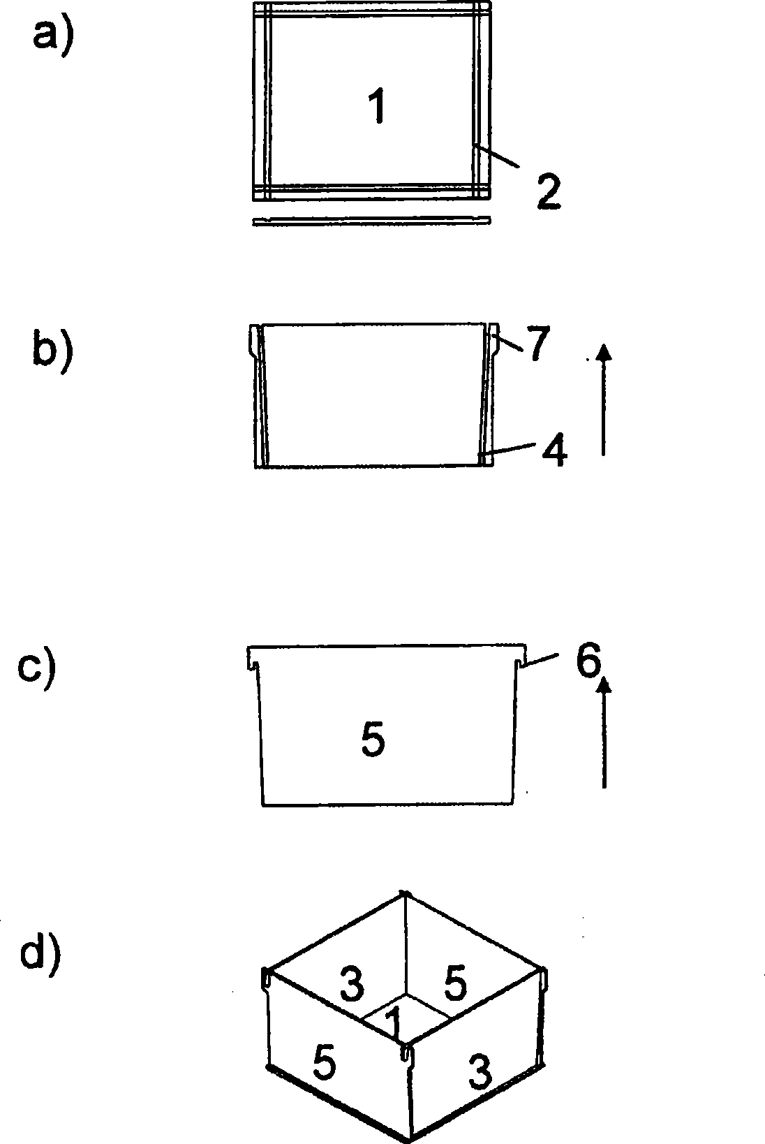
[0054] The crucible according to Example 1 is schematically represented in figure 1 a~1d.

[0055] figure 1 a shows a base plate 1 which is a square plate with grooves 2 along each side on its upward facing surface. The grooves correspond to the thickness of the side elements forming the walls of the crucible so that the lower edges of the side walls can enter the grooves and form a tight fit. Alternatively, said side elements and bottom grooves have complementary shapes, such as ploughs and tongues.

[0056] figure 1 b shows a rectangular wall element 3 . Two of these elements will be used on opposite sides, see figure 1 d. The side element 3 has grooves 4 on both sides along the surface towards the inner surface of the crucible. The groove 4 is dimensioned such that it fits closely with the sides of the wall element 5 , which is placed vertically relative to the wall element 3 . The groove 4 and the sides of the wall element 3 may have a congruent angled orientation ...

Embodiment 2

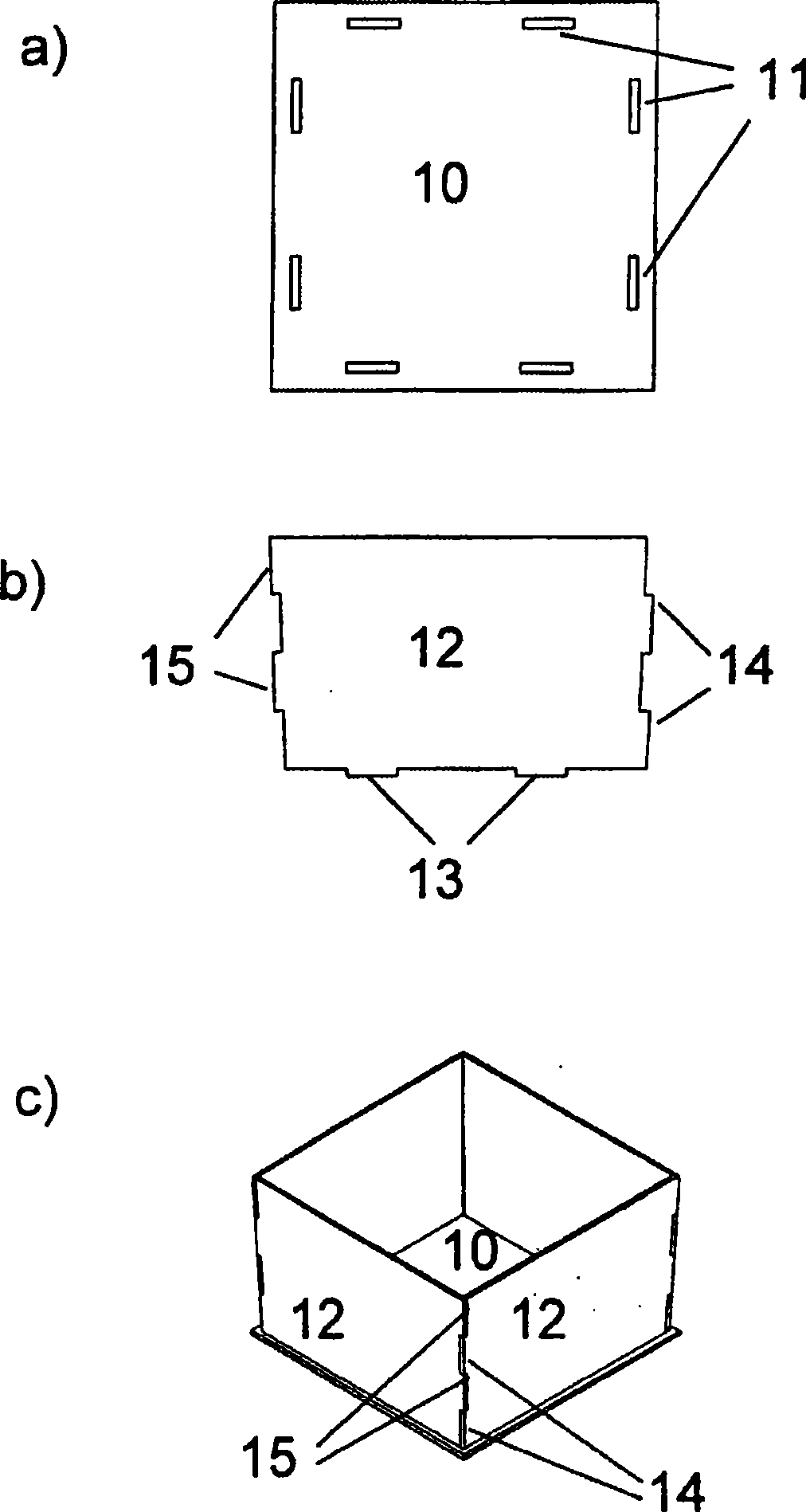
[0060] The crucible according to Example 2 is shown in figure 2 a~2c.

[0061] figure 2 a shows the bottom plate 10, which is a square plate with elongated holes 11 along each side thereof. The holes are sized so that they accommodate the sidewall protrusions facing downward and form a tight fit. It is also foreseen to include a groove (not shown) aligned with the central axis of the hole 11 , similar to the groove 2 of the bottom plate 1 of the first embodiment.

[0062] figure 2 b shows a wall element 12 . There are four of these elements, see figure 2 c. The wall element 12 has two protrusions 14 , 15 and two downward protrusions 13 on each side. The side projections are dimensioned such that when the two wall elements 12 are assembled to form adjacent walls of the crucible, the projections 14 enter the spaces between the projections 15 and form a tight fit. The downward facing projection 13 is sized to fit the hole 11 and form a tight fit, see figure 2 c. Th...

Embodiment 3

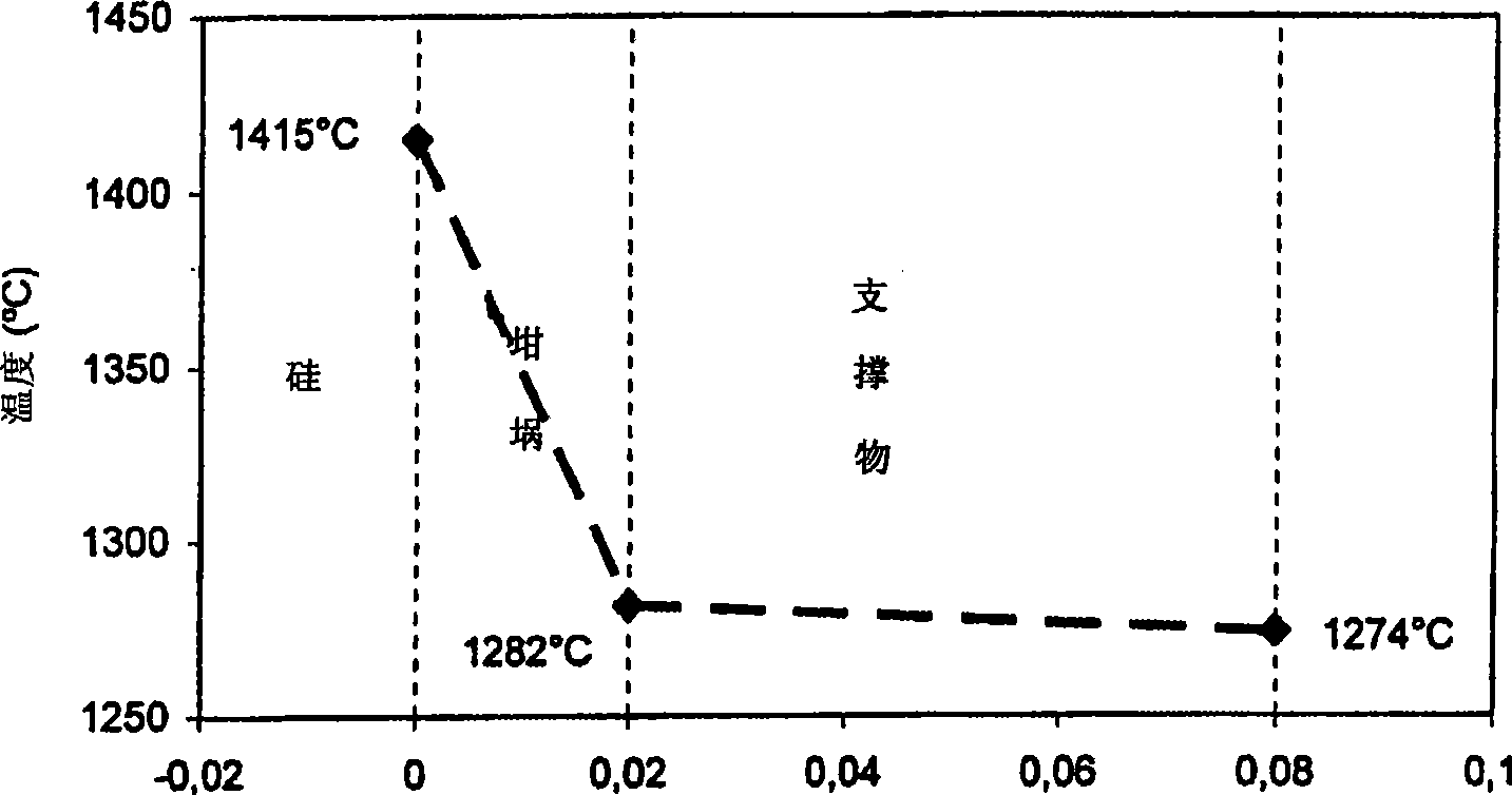
[0066] Example 3 Calculation of temperature distribution in a furnace using prior art quartz crucibles image 3 The steady-state one-dimensional temperature gradient calculated at the onset of crystallization using the standard furnace method is shown in . The temperature inside the bottom of the crucible was 1415°C. The bottom of the crucible is 2 cm thick and has a thermal conductivity of 1.5 W / mK. The support plate is 60mm thick and its thermal conductivity is 80W / mK. To remove 10kW / m 2 , the temperature at the bottom of the support plate must be lower than 1398°C. This heat transfer rate can provide a crystallization rate of up to 0.9 cm / h, depending on the heat transferred from the top chamber.


PUM

PropertyMeasurementUnit
thicknessaaaaaaaaaa

Abstract

This invention relates to a method for direct solidification of semiconductor grade multi-crystalline silicon ingots allowing improved control with the solidification process and reduced levels of oxygen and carbon impurities in the ingot, by crystallizing the semiconductor grade silicon ingot, optionally also including the melting of the feed silicon material, in a crucible made of silicon nitride, or in a crucible made of a composite of silicon carbide and silicon nitride, and where the wall thickness of the bottom of the crucible is dimensioned such that the thermal resistance across the bottom is reduced to a level of at least the same order as thermal resistance across the support below carrying the crucible or lower. The invention also relates to crucibles which are made of silicon nitride, or of a composite of silicon carbide and silicon nitride, and where the wall thickness of the bottom of the crucible is dimensioned such that the thermal resistance across the bottom is reduced to a level of at least the same order as thermal resistance across the support below carrying the crucible or lower.

Description

technical field [0001] The present invention relates to a method for directionally solidifying semiconductor grade polysilicon ingots which improves the control of the solidification process and reduces the content of oxygen and carbon impurities in the ingot. The invention also relates to a crucible enabling the implementation of said method. Background technique [0002] Over the next few decades, the world's oil supply will gradually dry up. This means that the main energy source of the last century must be replaced within a few decades to meet the current energy consumption and the increase in global energy demand in the future. [0003] In addition, there is great concern that the use of fossil energy sources increases the global warming effect to such an extent that it may become dangerous. Therefore, it should be preferred to replace currently consumed fossil fuels with energy sources / carriers that are renewable and sustainable for the climate and the environment. ...

Claims


Application Information

Patent Timeline
Patent Type & Authority Applications(China)
IPC IPC(8): C30B29/06C30B11/00
CPCC30B11/002C30B29/06C30B11/00F27B14/10
Inventor 施泰因·朱尔斯鲁德蒂克·劳伦斯·纳斯
Owner REC SCANWAFER
Why Eureka
Try Eureka