Light distribution lens design method aiming at point light source

A light distribution lens and design method technology, applied in optics, optical components, mechanical equipment, etc., can solve problems that are not well solved, have many formulas, and have high mathematical requirements

Inactive Publication Date: 2009-07-15
FUDAN UNIV
View PDF0 Cites 52 Cited by
  • Summary
  • Abstract
  • Description
  • Claims
  • Application Information

AI Technical Summary

Problems solved by technology

However, this problem has not been well resolved
However, the cutting method requires high mathematics, and there are many formulas and each formula is very complicate

Method used


Image

  • Light distribution lens design method aiming at point light source
  • Light distribution lens design method aiming at point light source
  • Light distribution lens design method aiming at point light source

Examples


Embodiment 1

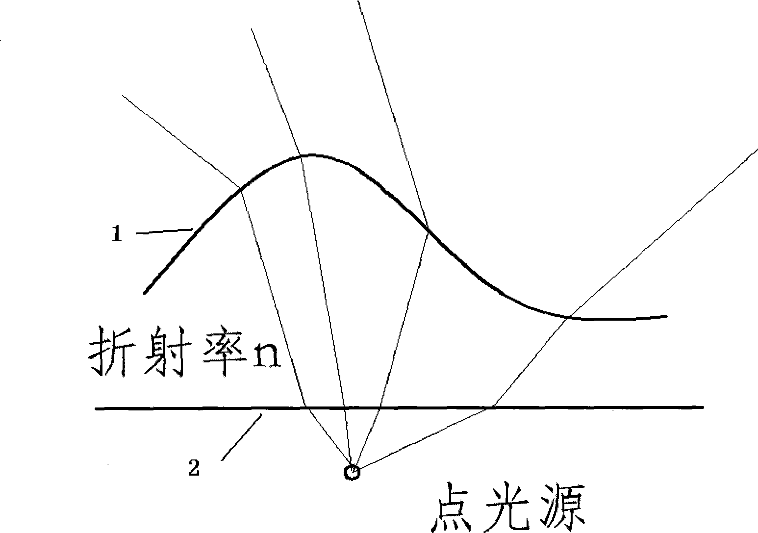
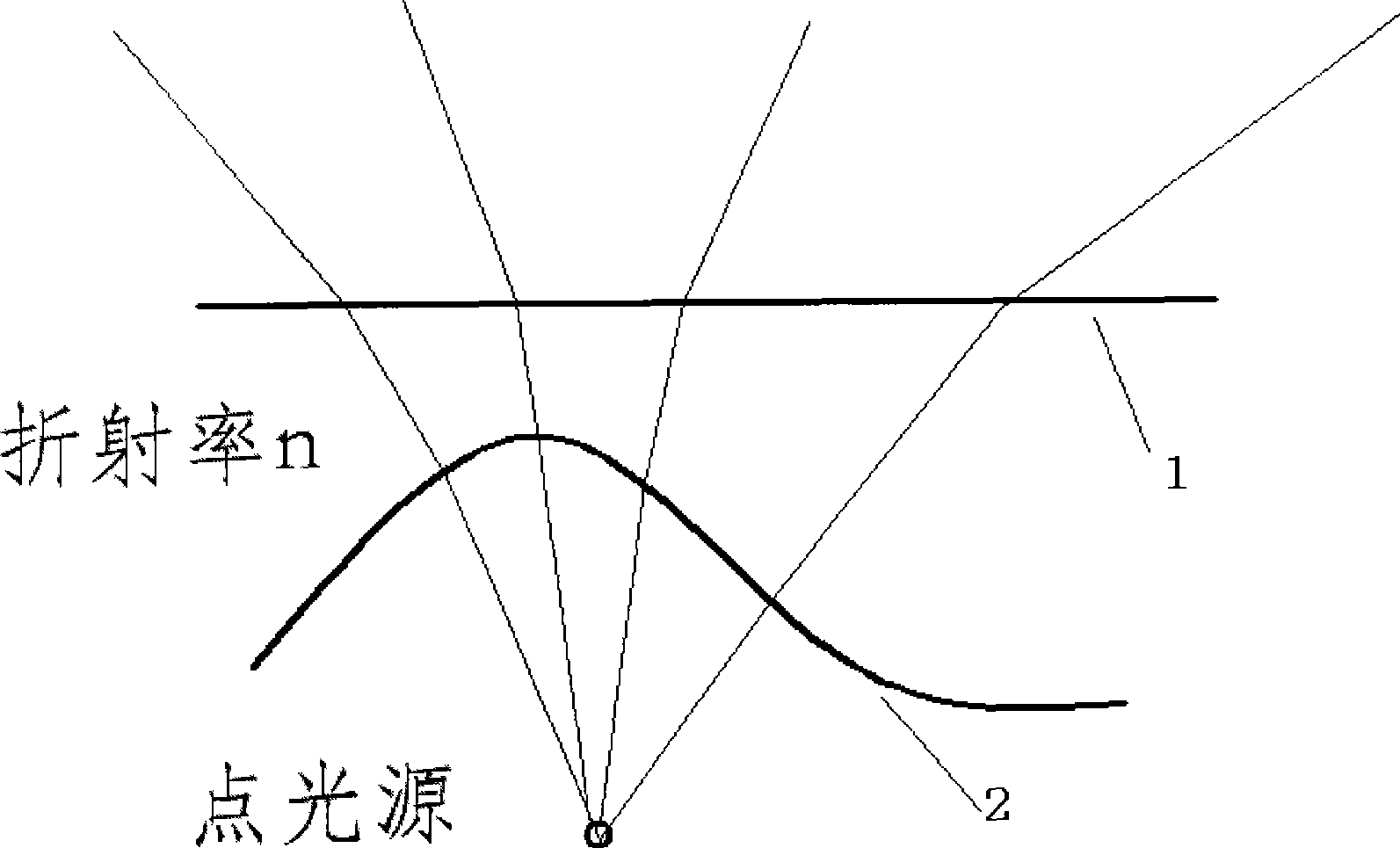
[0074] Embodiment 1: the initial structure that the lens is intended to take is as attached figure 2 As shown, the inner surface 2 adopts a spherical surface, and the outer surface 1 is a free-form surface. Therefore, the focus of this design is how to design the outer surface of the lens. The energy of the incident light and the energy of the outgoing light correspond to the longitude and latitude, such as Image 6 . The light source adopts Lambertian LED, that is, I(α)=I cos(α), and I is the central light intensity. The center point of the lens is required to be P(10mm, 0, 0). The observation surface is placed 10 meters away, and it is required to form a rectangular uniform spot with a length of 30 meters and a width of 10 meters, and its center is on the y-axis.

[0075] First, place the LED at the origin of the coordinate system so that its central axis coincides with the y-axis. The light intensity distribution of the known LED is I(α)=I cos(α), expressed in the coo...

Embodiment 2

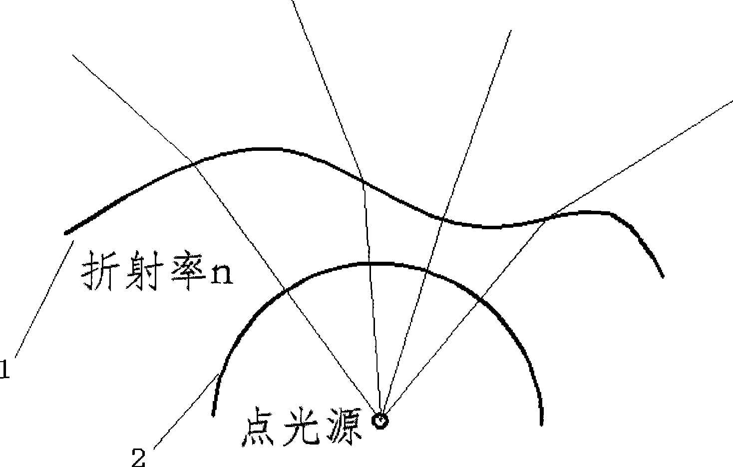
[0093] Embodiment 2: the initial structure that lens adopts is as attached image 3 shown. The outer surface adopts a plane, and the inner surface adopts a free-form surface. This initial structure is relatively complex. Because the ray is deflected twice, the index of refraction formula is used twice. The corresponding relationship between the incident light and the outgoing light is Image 6 The radiating annulus shown corresponds to . After two iterations of the refraction index vector formula, the formula is listed for simplified numerical solution, and the surface is drawn to form a solid diagram, as shown in the attached Figure 13 shown. The outer surface of the lens is flat, and the inner surface is formed by splicing four discontinuous fan-like shapes.

Embodiment 3

[0094] Embodiment 3: the initial structure that lens adopts is as attached image 3 shown. The outer surface adopts a plane, and the inner surface adopts a free-form surface. The corresponding relationship between the incident light and the outgoing light is Figure 5 The latitude and longitude grids shown correspond. After two iterations of the refractive index vector formula, the formula is listed for simplified numerical solution, and the surface diagram is drawn as attached Figure 14 shown. The outer surface of the lens is plane, and the inner surface is a curved surface similar to a saddle.


PUM


Abstract

The invention belongs to non-imaging optical technical field, especially relates to a design method aiming at a spot light source (such as LED) light distribution lens. The invention adopts a free curved surface design method, selects an appropriate energy corresponding relationship, sets a reasonable structure form of the lens, under assistance of the computer, can design the lens satisfying the requirement, after the light source passes through the light distribution lens, the light spot can reach to the expected distribution, such as an even rectangle light spot. The certain surface of the light distribution surface (inner surface or outer surface) is a free curved surface and is generated by the calculated numerical value points. The light distribution lens can be made by injection moulding machining with optical resin and so on materials, the method comprises: arranging the spot light source on the center of the inner surface of the light distribution lens and taking the combination as a unit; increasing or decreasing the unit numbers of the units according to the light energies required by the target surface. In addition, the light distribution lens can also be made into an array form to enable the one light distribution lens to be provided with a plurality of lens units.

Description

technical field [0001] The invention belongs to the technical field of non-imaging optics and illumination, and in particular relates to a design method for a light distribution lens of a point light source (such as an LED). Background technique [0002] It is a classic problem in the lighting field that a point light source (such as LED) passes through the lens to form a specific spot that meets the lighting needs. However, this problem has not been well resolved. Because the lenses used in optical design are generally spherical or parabolic or ellipsoidal lenses, that is to say, they are all regular structures. Of course, some people also use aspherical lenses, but these lenses are all rotationally symmetrical structures around the central axis. If the designed lens is required to achieve a rectangular spot or other more complex non-centrosymmetric spots, these lenses are often powerless. [0003] In recent decades, with the development of the subject of solar energy co...

Claims


Application Information

Patent Timeline
IPC IPC(8): G02B27/00F21V5/04
CPCF21W2131/103
Inventor 刘木清江程江磊陈郁阳周小丽沈海平
Owner FUDAN UNIV
Why Eureka
Try Eureka