Main spindle transmission control system of economy type numerically controlled lathe

A CNC lathe and spindle transmission technology, applied in metal processing equipment, etc., can solve the problems of inconsistent roughness of the processed surface, the inability of stepless speed regulation of the spindle, and the inability of wide-range speed regulation of the spindle to achieve simple operation and automation High, easy maintenance effect

Inactive Publication Date: 2009-07-22
FUJIAN CHENGGONG MACHINE TOOL CO LTD
View PDF6 Cites 0 Cited by
  • Summary
  • Abstract
  • Description
  • Claims
  • Application Information

AI Technical Summary

Problems solved by technology

Due to the small speed difference between the adjacent gears of the gear box, the spindle cannot be adjusted in a wide range. When the lathe is to turn a large-diameter circular plane, the linear speed of the tool tip (spindle speed) cannot follow the change of the cutting diameter. However, the spindle cannot be adjusted steplessly, the surface roughness of the workpiece is inconsistent, and the turning process of large-diameter workpieces cannot be realized.

Method used


Image

  • Main spindle transmission control system of economy type numerically controlled lathe

Examples


Embodiment Construction

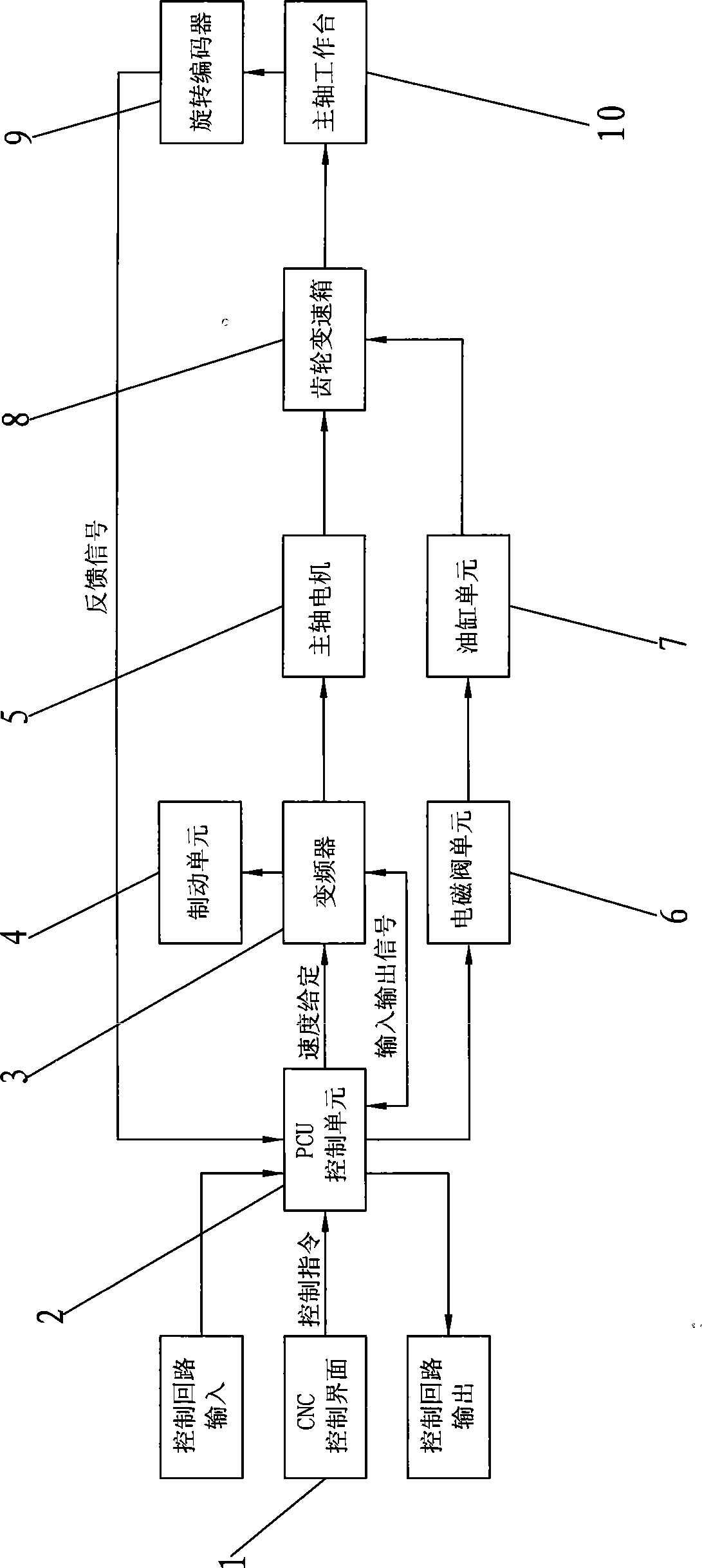
[0009] The spindle drive control system of the economical CNC lathe of the present invention, such as figure 1 As shown, it includes CNC control interface 1, PCU control unit 2, frequency converter 3, braking unit 4, spindle motor 5, solenoid valve unit 6, oil cylinder unit 7, gear box 8 and rotary encoder 9. The CNC control interface 1 is connected to the setting input terminal of the PCU control unit 2, and the control output terminal of the PCU control unit 2 is connected to the frequency converter 3, the spindle motor 5 and the gear box 8 in turn, and the brake unit 4 (the brake unit mainly starts the spindle stop energy consumption braking) is connected to the brake control output terminal of the inverter 3, and the analog output terminal of the PCU control unit 2 is bidirectionally connected with the analog input terminal of the inverter 3 to realize the input and output of control signals; the PCU control unit The other output end of 2 is connected to the solenoid valve...


PUM


Abstract

The invention discloses a main shaft transmission control system for an economic numerically controlled lathe, which comprises a CNC control interface, a PCU control unit, a main shaft motor, a solenoid valve unit, an oil cylinder unit, a transmission gear box and a rotary encoder, wherein the transmission gear box is a transmission gear box which adopts a shifting slide gear and is provided with a shifting fork. The main shaft transmission control system for the economic numerically controlled lathe also comprises a frequency converter and a braking unit, wherein the frequency converter is connected between the output end of the PCU control unit and the input end of the main shaft motor; and the braking unit is connected with a brake control output end of the frequency converter. Compared with the prior art, the main shaft transmission control system for the economic numerically controlled lathe adopts the frequency converter to realize speed regulation of a main shaft; the regulation range of frequency control is wide, and general frequency converters can realize stepless speed regulation within a range between 0 and 400 Hz, so that the main shaft transmission control system can meet the requirements of constant-speed cutting of a numerical control system and stepless speed changing of the rotating speed of the main shaft; and the rotating speed of the main shaft is varied along with the variation of the diameter of the current processing workpiece, so that the cutting linear speed on a cutting point of a tool can be always guaranteed to be constant, and turning technology of large-diameter workpieces can be realized.

Description

technical field [0001] The invention relates to an economical numerical control lathe, in particular to a spindle transmission control system of the economical numerical control lathe. Background technique [0002] The main shaft of an ordinary economical CNC lathe is driven by an asynchronous motor to drive a gear box with 4 oil cylinders and 16 stages of hydraulic transmission to drive and adjust the speed. Its transmission control system includes CNC control interface, PCU control unit, spindle motor, solenoid valve unit, oil cylinder mechanism unit, gear gearbox, manual rotary valve, shift button and rotary encoder, and writes processing instructions to the PCU control unit through the CNC control interface , the PCU control unit is connected to the spindle motor through the bus output control signal to control the operation of the spindle motor. When adjusting the speed, you need to manually rotate the manual rotary valve to select the required gear, and then press the...

Claims


Application Information

Patent Timeline
IPC IPC(8): B23B19/02
Inventor 曹先强赖安业
Owner FUJIAN CHENGGONG MACHINE TOOL CO LTD
Why Eureka
Try Eureka