Robot joint drive system

A driving device and robot technology, applied in the direction of electromechanical devices, transmission devices, gear transmission devices, etc., can solve the problems of undisclosed motor and reducer storage, and achieve the effect of reducing the occupied volume and easy inventory

Active Publication Date: 2009-07-22
SUMITOMO HEAVY IND LTD
View PDF1 Cites 16 Cited by
  • Summary
  • Abstract
  • Description
  • Claims
  • Application Information

AI Technical Summary

Problems solved by technology

At present, in Patent Document 1, for example, specific techniques for more compact storage of the motor and the speed reducer have not been disclosed.

Method used


Image

  • Robot joint drive system
  • Robot joint drive system
  • Robot joint drive system

Examples


Embodiment Construction

[0021] Hereinafter, an example of an embodiment of the present invention will be described in detail with reference to the drawings.

[0022] First, refer to Figure 4 The overall structure will be described in general. Figure 4 It is a schematic plan view and a side view showing a case where a robot joint drive device according to an example of an embodiment of the present invention is used for a robot arm.

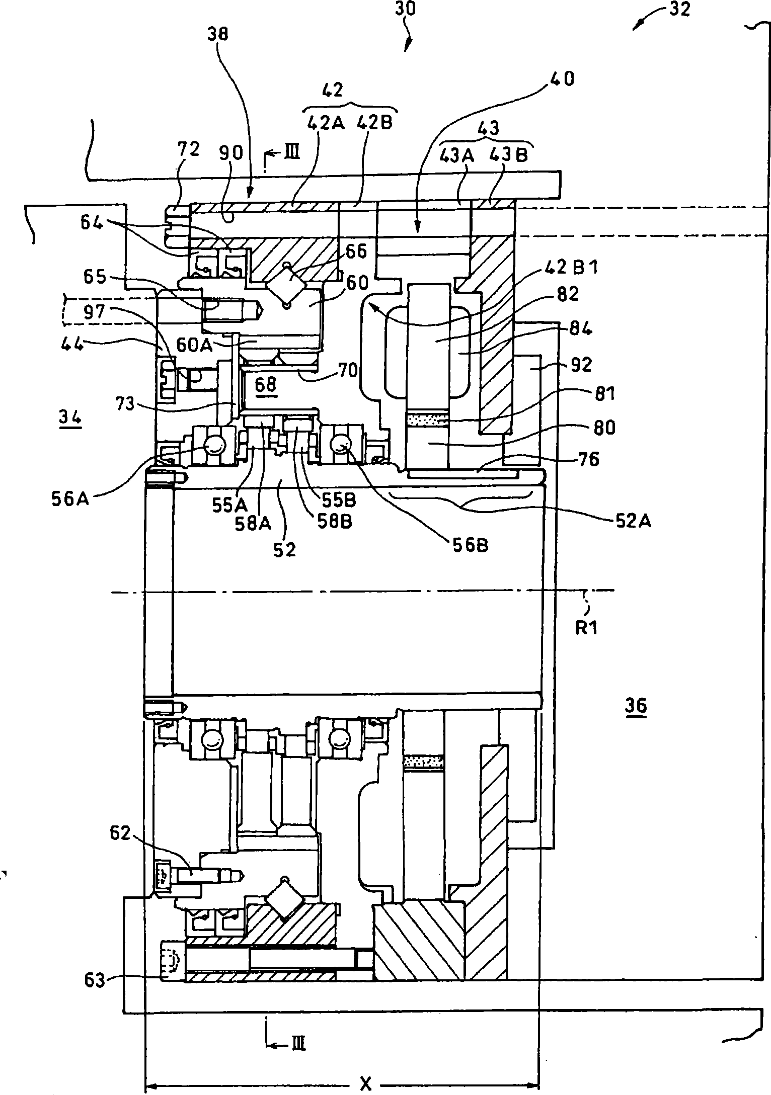
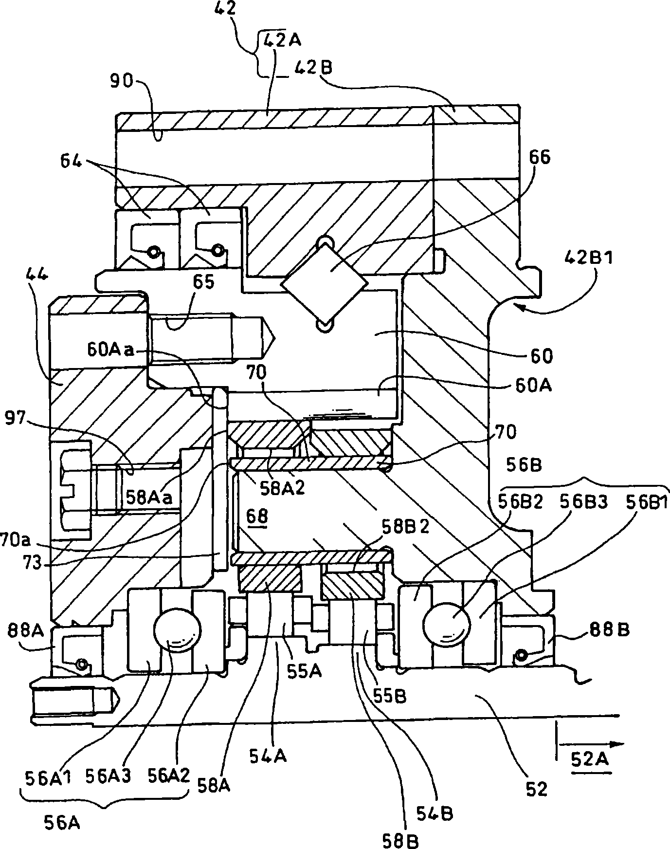
[0023] This robot joint driving device 30 has a speed reducer 38 and a flat motor 40, and drives a first member 34 and a second member 36 of an arm 32 of a robot (not shown in its entirety) to rotate relative to each other. The first member 34 is fixed to an output flange (output shaft) 44 of the speed reducer 38 . The speed reducer case 42 is fixed to the second member 36 via the motor case 43 . The output flange 44 of the speed reducer 38 is relatively rotatable around the rotation axis R1 with respect to the speed reducer case 42 . Therefore, as a result, the fir...


PUM


Abstract

The invention provides a robot joint drive system (30) that in particular enables size reduction that makes feasible the realization of a robot joint. The joint driving device includes a flat motor (40) and a reducer (38) for driving a first member (34) and a second member (36) of a robot relative to each other. An output flange (an output shaft) (44) of the reducer (38) is secured to the first member (34), while a casing (42) of the reducer is secured to the second member (36) (through a motor casing (43)). An input shaft (52) of the reducer (38) includes a cantilevered protruded part (52A) projecting from the casing (42) of the reducer in a cantilevered manner, and a rotor (80) of the flat motor (40) is secured to this cantilevered protruded part (52A).

Description

technical field [0001] The present invention relates to a joint driving device of a robot, which has a motor and a speed reducer, and drives a first member and a second member of the robot to rotate relative to each other. Background technique [0002] In recent years, in the manufacturing industry, the development of robots that perform actions infinitely close to those operated by humans, such as "dual-arm robots", has become active. In the case of robots, to achieve rotation about a single axis, one joint is required in each respective axis. Therefore, in order to replace human operations with a robot to perform the same motion as a human, it is necessary to configure more joints than human joints. Therefore, if the individual joints are not stored as compactly as possible, the volume occupied by the joints will be relatively large relative to the effective length (movable range) of the arm, and the appearance will be very different from that of a human arm. It becomes ...

Claims


Application Information

Patent Timeline
Patent Type & Authority Applications(China)
IPC IPC(8): B25J19/00B25J17/00F16H1/20F16H57/02F16H1/32H02K7/116
CPCB25J9/102F16H1/32F16H57/021H02K7/116Y10T74/20317B25J9/06B25J18/00
Inventor 山本章田村光扩志津庆刚
Owner SUMITOMO HEAVY IND LTD
Why Eureka
Try Eureka