Synchronous collection and conversion device for wave kinetic potential

A conversion device and technology of potential energy are applied in the field of wave kinetic potential energy synchronous collection and conversion device, which can solve the problems of insufficient collection and utilization of wave energy, and achieve the effects of simple structure, low requirements on manufacturing precision and convenient installation.

Inactive Publication Date: 2009-07-22
SHAANXI NORMAL UNIV
View PDF2 Cites 16 Cited by
  • Summary
  • Abstract
  • Description
  • Claims
  • Application Information

AI Technical Summary

Problems solved by technology

The above-mentioned wave energy absorbing and collecting device can only collect and convert the potential energy of waves, so it has the problem of insufficient collection and utilization of wave energy.

Method used


Image

  • Synchronous collection and conversion device for wave kinetic potential
  • Synchronous collection and conversion device for wave kinetic potential
  • Synchronous collection and conversion device for wave kinetic potential

Examples


Embodiment 1

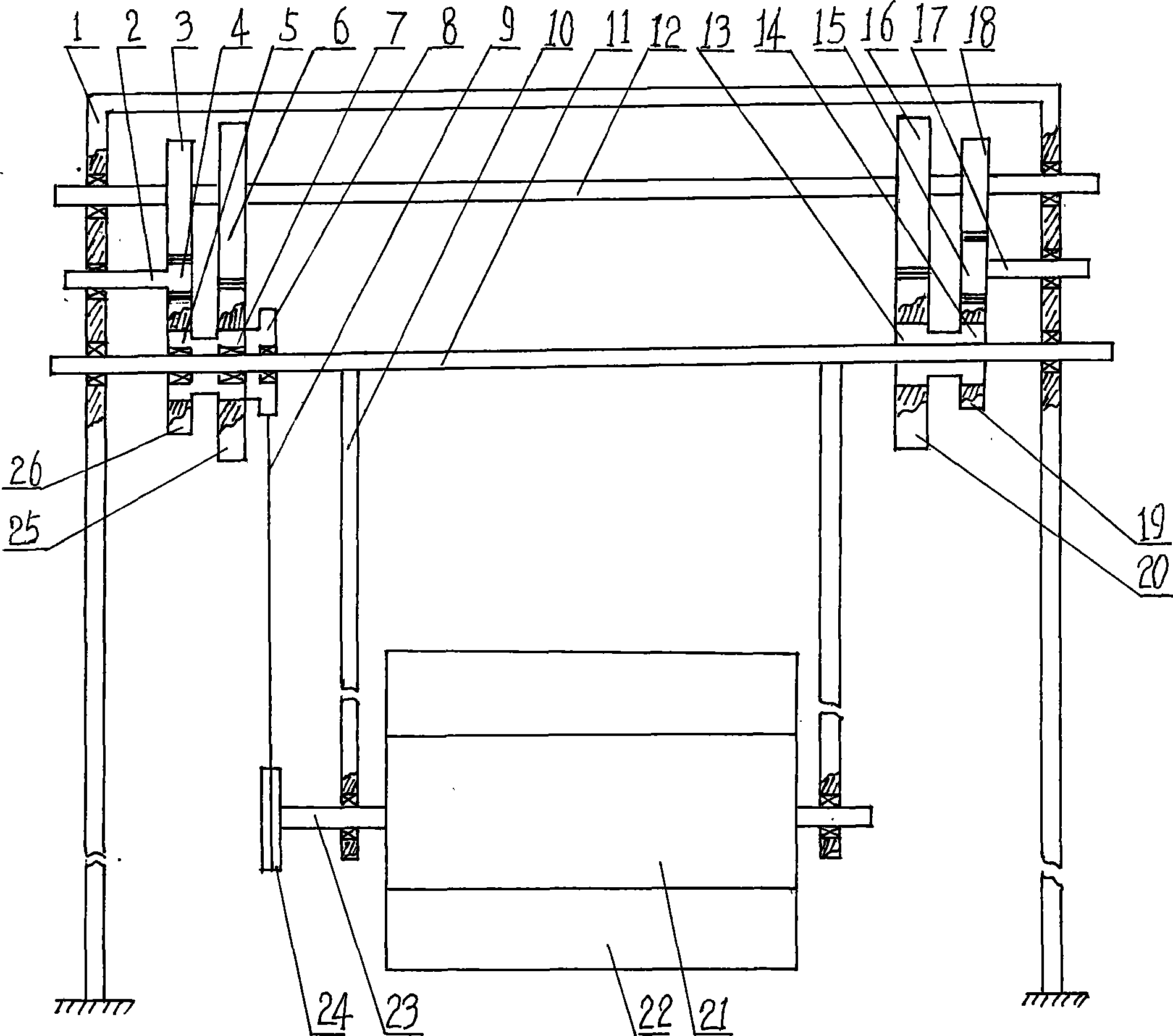
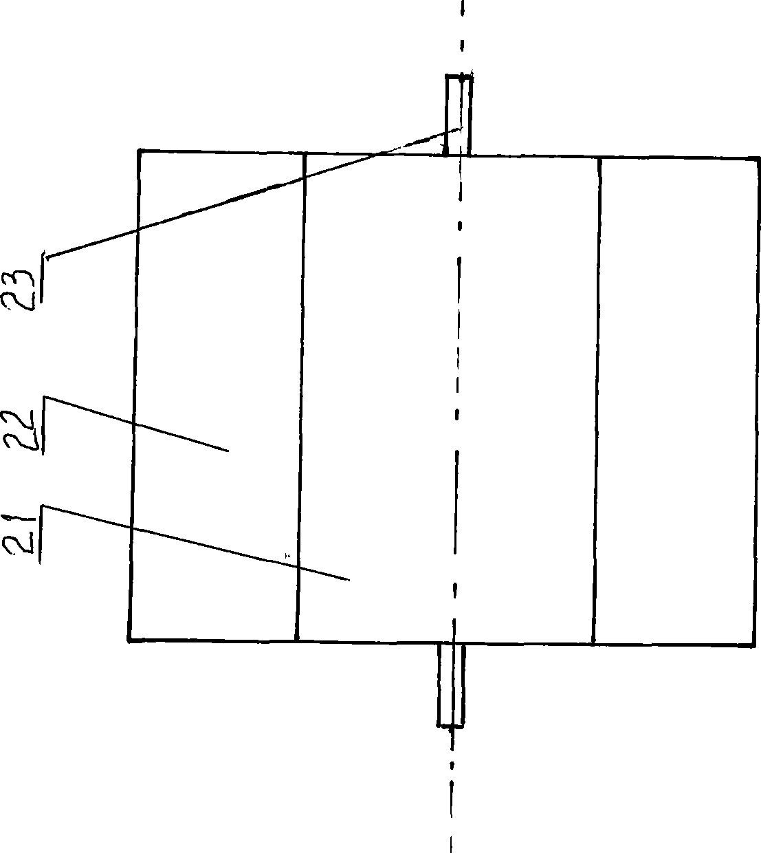
[0018] exist figure 1 , 2 , 3, the wave kinetic potential energy synchronous collection conversion device of the present embodiment is composed of support 1, kinetic energy reversing shaft 2, kinetic energy left driven gear 3, kinetic energy reversing gear 4, kinetic energy left ratchet 5, kinetic energy right driven gear 6, Kinetic energy right ratchet 7, driven sprocket 8, chain 9, swing lever 10, input shaft 11, output shaft 12, potential energy left ratchet 13, potential energy right ratchet 14, potential energy reversing gear 15, potential energy left driven gear 16, potential energy Reversing shaft 17, potential energy right driven gear 18, potential energy right driving gear 19, potential energy left driving gear 20, float 21, blade 22, float shaft 23, driving sprocket 24, kinetic energy right driving gear 25, kinetic energy left driving gear 26 Connection structure, wherein buoys 21, blades 22, and buoy shafts 23 are connected to form a kinetic energy collection wheel...

Embodiment 2

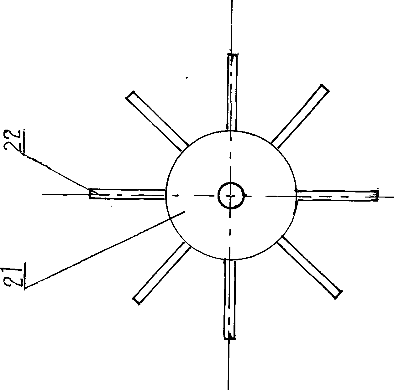
[0024] In this embodiment, the shape of the buoy 21 is cylindrical, and the outer surface of the cylinder of the buoy 21 is radially uniformly welded with two blades 22, and the angle between one blade 22 and the adjacent blade 22 is 180°. Other components and the coupling relationship of the components are the same as in Embodiment 1.

Embodiment 3

[0026] In this embodiment, the shape of the buoy 21 is cylindrical, and the outer surface of the cylinder of the buoy 21 is radially uniformly welded with 12 blades 22, and the angle between one blade 22 and the adjacent blade 22 is 30°. Other components and the coupling relationship of the components are the same as in Embodiment 1.

[0027] The working principle of the present invention is as follows:

[0028]During use, the lower end of the support 1 of the present invention is fixedly installed on the seabed, so that the buoy 21 floats on the sea surface. When the waves move forward or backward, the blades 22 are impulsed. Rotate clockwise or counterclockwise and move up and down, driving sprocket 24 drives driven sprocket 8 to rotate clockwise or counterclockwise through chain 9, kinetic energy right ratchet 7, kinetic energy left ratchet 5 rotate clockwise or counterclockwise. When the kinetic energy right ratchet 7 and the kinetic energy left ratchet 5 rotate clockwise...


PUM


Abstract

The invention discloses a synchronous wave kinetic potential energy collection and conversion device. In the device, a support is provided with an input shaft, a kinetic energy reversing shaft, a potential energy reversing shaft and an output shaft; the input shaft is provided with a swinging rod, a buoy shaft arranged on a buoy is arranged on the swinging rod, the buoy is provided with blades, the left side of the input shaft is provides with a driven chain wheel, a right kinetic energy ratchet wheel and a right kinetic energy ratchet wheel, the driven chain wheel is connected with a driving chain wheel arranged on the buoy shaft by a chain, the right side of the input shaft is provided with a left potential energy ratchet wheel and a right potential energy ratchet wheel, the kinetic energy reversing shaft is provided with a kinetic energy reversing gear engaged with a left kinetic energy driving gear, the potential energy reversing shaft is provided with a potential energy reversing gear engaged with a right potential energy driving gear, the left side of the output shaft is provided with a left kinetic energy driven gear engaged with the kinetic energy reversing gear and a right kinetic energy driven gear engaged with the right kinetic energy driving gear, and the right side of the output shaft is provided with a right kinetic energy driven gear engaged with the potential energy reversing gear and a left potential energy driven gear engaged with the left potential energy driving gear. The device can convert kinetic energy and potential energy of waves into rotation energy in a definite direction.

Description

technical field [0001] The invention belongs to the technical field of marine wave energy power generation, and in particular relates to a device for synchronous collection and conversion of wave kinetic potential energy. Background technique [0002] With the increasing shortage of traditional mineral energy and the increasingly serious environmental pollution caused by the extensive use of mineral energy, many countries in the world have taken vigorous research and development of environmentally friendly and clean energy such as ocean energy, solar energy, and wind energy as an important part of their national energy strategy. component. "Efficient development and utilization of marine resources" has also been included as a development and research project in my country's "medium and long-term scientific and technological development plan outline". Ocean energy includes tidal energy, ocean current energy, sea surface solar energy, wind energy, wave energy, temperature dif...

Claims


Application Information

Patent Timeline
Patent Type & Authority Applications(China)
IPC IPC(8): F03B13/22
CPCY02E10/38Y02E10/30
Inventor 张宗权杨宗立
Owner SHAANXI NORMAL UNIV
Why Eureka
Try Eureka