
Cold-resistant pressure-bearing solar heat-collection and energy-storage pipe with electric heating function

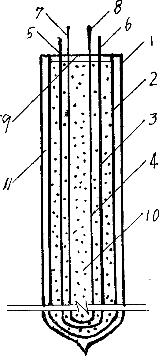
A technology of solar heat collection and electric heating, applied in the direction of solar heat energy, solar heat collector, solar heat collector using working fluid, etc. Collecting water capacity and energy storage in the collector tube can solve the problem of solar energy and building integration design, solve industrial technical problems, and reduce the weight of the whole machine.

Inactive Publication Date: 2009-07-22
何立昌 +1
View PDF5 Cites 0 Cited by
  • Summary
  • Abstract
  • Description
  • Claims
  • Application Information

AI Technical Summary

Problems solved by technology

[0002] In the prior art, there are very few documents related to the use of solar collector tubes for energy storage. The two patents with the published patent Nos. However, the diameter of the heat collecting tube cannot be too large. At the same time, increasing the water capacity of the heat collecting tube to store energy does not actually reduce the weight of the solar water heater. It just removes the water tank and transfers the water capacity of the water tank to the thickened one. In the heat collecting tube, moreover, because water is sensible heat storage energy, in sunny weather, the water temperature in the heat collecting tube will quickly exceed the scaling point of water by 60°C, and then cause hard scale on the inner wall of the heat collecting tube, making the heat collector The heat collection performance is declining year by year, so the large-diameter heat collecting tubes in the prior art are used as the heat collecting elements of the tankless solar water heater, and cannot really be applied to the complete machine of the tankless solar water heater. machine didn't come out

Method used


Image

  • Cold-resistant pressure-bearing solar heat-collection and energy-storage pipe with electric heating function

Examples


Embodiment 1

[0012] Example 1, when the melting point of the added phase-change energy storage material is at 45-60°C, it can replace the commonly used heat collectors in roof-mounted, wall-mounted, wall-mounted and balcony railing-mounted waterless tanks The solar water heater can also be used on the module in the central heating water supply project, canceling the water tank in the hot water project.

Embodiment 2

[0013] Example 2, when the melting point of the added phase-change energy storage material is 105-110°C, it can be used in a solar water boiler.

Embodiment 3

[0014] Example 3, when the melting point of the added phase change energy storage material is 110-200°C, it can be used as a heat source for a solar thermal power plant.


PUM

PropertyMeasurementUnit
Melting pointaaaaaaaaaa

Abstract

The invention discloses a cold-resistant pressure-bearing solar heat collecting and energy storing tube which has the electrical heating function, aiming at providing a series of heat collecting and energy storing tubes to replace the existing popular conventional single open-ended evacuated tube solar collector and to be applied to solar water heater without water tank. The heat collecting and energy storing tube comprises a single open-ended evacuated tube solar collector and a sealing cover, wherein, a phase-transition energy storing material, a copper-pipe heat exchanger and an electrical heating wire are installed in an inner cylindrical cavity of the single open-ended evacuated tube solar collector. The copper pipe of the heat exchanger in the inner cylindrical cavity of the solar collector extends to the position 2cm away from the capped end of the inner pipe and two ends of the copper pipe penetrate the sealing cover. The electrical heating wire in the inner cylindrical cavity of the evacuated tube solar collector extends to the position 3cm away from the capped end of the inner pipe, and the negative and the positive electrodes of the wire penetrate the sealing cover. The invention replaces the popular single open-ended evacuated tube solar collector, and can be used for manufacturing roof-typed, wall-mounted, wall-embedded, or balcony railing panel embedded solar water heater without water tank. The invention can be widely applied to the integrated construction of solar energy and buildings.

Description

technical field [0001] The invention relates to a solar water heater, in particular to a multifunctional heat collecting tube matched with a tankless solar water heater. Background technique [0002] In the prior art, there are very few documents related to the use of solar collector tubes for energy storage. The two patents with the published patent Nos. However, the diameter of the heat collecting tube cannot be too large. At the same time, increasing the water capacity of the heat collecting tube to store energy does not actually reduce the weight of the solar water heater. It just removes the water tank and transfers the water capacity of the water tank to the thickened one. In the heat collecting tube, moreover, because water is sensible heat storage energy, in sunny weather, the water temperature in the heat collecting tube will quickly exceed the scaling point of water by 60°C, and then cause hard scale on the inner wall of the heat collecting tube, making the heat co...

Claims


Application Information

Patent Timeline
IPC IPC(8): F24J2/05F24J2/34F24S10/40
CPCY02B10/22Y02E10/44Y02B10/20
Inventor 何立昌朱亚剑
Owner 何立昌
Learn More