Permanent magnet rotating machine

A rotating machine and permanent magnet technology, applied in the direction of magnetic circuit rotating parts, magnetic circuit shape/style/structure, etc., can solve the problem of increasing magnetic flux and achieve the effect of improving efficiency

Active Publication Date: 2009-07-22
AICHI ELECTRIC
View PDF1 Cites 19 Cited by
  • Summary
  • Abstract
  • Description
  • Claims
  • Application Information

AI Technical Summary

Problems solved by technology

However, the above-mentioned conventional permanent mag

Method used


Image

  • Permanent magnet rotating machine
  • Permanent magnet rotating machine
  • Permanent magnet rotating machine

Examples


Embodiment Construction

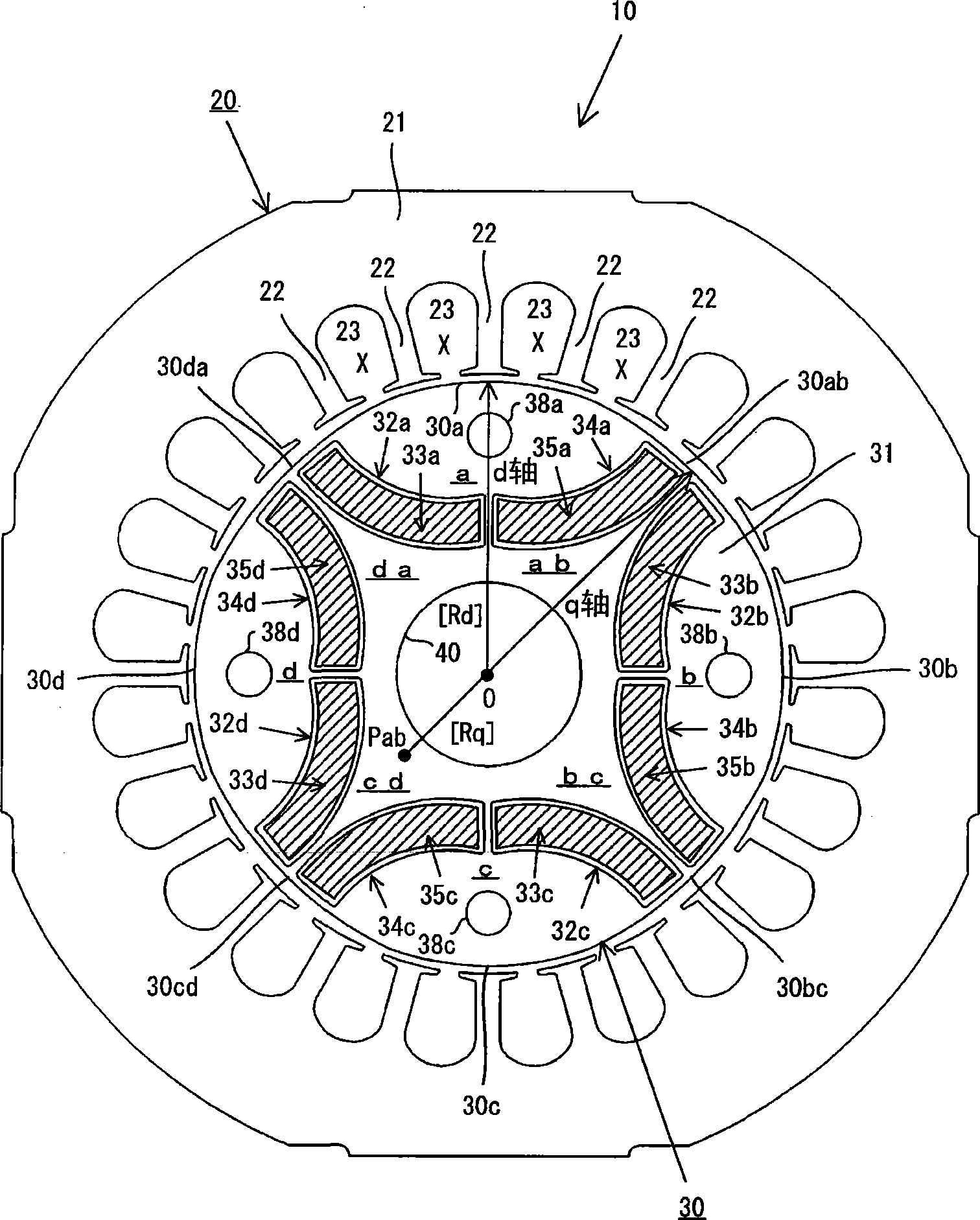
[0058] Conventionally, in permanent magnet motors, rare earth magnets (rare earth magnets) having a high magnetic flux density have been used. In particular, neodymium magnets containing Nd (neodymium), Fe (iron), Co (cobalt), B (boron) and the like are used. However, since rare earth magnets such as neodymium magnets are expensive, it is necessary to develop a permanent magnet motor using an inexpensive permanent magnet. Permanent magnet motors such as ferrite magnets.

[0059] In a permanent magnet motor in which permanent magnets are inserted into magnet insertion holes provided in the main magnetic pole portion of the rotor, the magnetic flux depends on the length of the outer wall (wall on the outer peripheral surface) of the magnet insertion hole. Therefore, when using a magnet with a low magnetic flux density such as a ferrite magnet, compared with the case of using a rare-earth magnet with a high magnetic flux density, in order to obtain a permanent magnet motor with ...


PUM


Abstract

The invention provides a permanent-magnet rotating machine. A cirumferential of a rotor comprises a first curve part and a second curve part in different curvature radius. A first magnet holding hole for holding a first permanent magnet and a second magnet holding hole for holding a second permanent magnet are arranged on a main pole part. An outer wall and an inner wall of the first magnet holding hole are formed into an arc at the center of a center point. An outer wall and an inner wanll of the second magnet holding hole are formed into an arc at the center of a center point different from the center point. The magnetic orientation of the first permanent magnet (the second permanent magnet) converges to a central orientation center at the center, and converges to an end orientation center farther than central orientation center at the end.

Description

technical field [0001] The present invention relates to a permanent magnet rotary machine in which a permanent magnet is inserted into a magnet insertion hole provided in a rotor, and particularly relates to a technique for improving the efficiency of the permanent magnet rotary machine. Background technique [0002] As an electric motor that drives a compressor of an air conditioner (air conditioner) or a refrigerator (refrigerator), or drives a vehicle (motor vehicle) or an on-board device (apparatus installed in a motor vehicle), etc. For example, a permanent magnet motor (referred to as an "Interior Permanent Magnet Motor") in which a permanent magnet is inserted into a magnet insertion hole provided on a rotor can be used. Such a permanent magnet motor includes, for example, a stator provided with teeth, and a rotor rotatably arranged with a gap between tooth top surfaces. On the rotor, when viewed in cross section perpendicular to the axial direction of the rotor (whe...

Claims


Application Information

Patent Timeline
IPC IPC(8): H02K1/27
Inventor 大熊繁道木慎二富田睦雄佐藤光彦金子清一
Owner AICHI ELECTRIC
Why Eureka
Try Eureka