Optical head device, optical information device, computer, disc player, car navigation system, optical disc recorder, and vehicle
A technology of optical information and optical head, applied in the direction of optical recording head, beam guiding device, optical recording/reproduction, etc., can solve the problems of not being disclosed, and achieve wide dynamic range of shape, reliable focus servo, and small number of parts Effect
- Summary
- Abstract
- Description
- Claims
- Application Information
AI Technical Summary
Problems solved by technology
Method used
Image
Examples
Embodiment approach 1
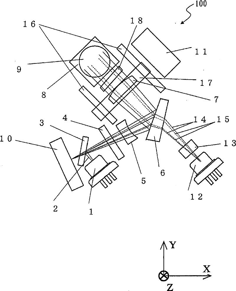
[0069] figure 1 The structure of the optical head device 100 of this embodiment is shown.
[0070] The optical head device 100 has semiconductor laser elements (hereinafter referred to as "light sources") that emit light beams of at least two different wavelengths, and is capable of recording and / or reproducing information on different types of optical discs. In the following description, an example will be described where there are three light sources and it is possible to record information and / or reproduce information on BD, DVD, and CD.
[0071] The optical head device 100 has: light source modules 1 and 12, parallel plate 3, holographic element 4, relay lens 5, wedge 6, collimator lens 7, erect mirror 8, objective lens 9, photodetector 10, diffraction element 13 and 1 / 4 wavelength plate 18 .
[0072] Next, the function of each component will be described while explaining the operation when the optical head device 100 radiates light. in, figure 1 The middle Y axis is...
Embodiment approach 2
[0129] Figure 8 The structure of the optical head device 200 of this embodiment is shown. Among the components of the optical head device 200, there are the same as the optical head 100 of Embodiment 1 ( figure 1 ) The constituent elements included in ) have the same functional elements are given the same reference symbols, and descriptions thereof are omitted.
[0130] The main difference is that a detection lens 501 is newly installed and an objective lens 25 is installed instead of the objective lens 9 .
[0131] The detection lens 501 is an anamorphic lens provided so that two orthogonal axes have different focal lengths, since the detection lens 501 performs focus error signal detection by the astigmatism method.
[0132] The objective lens 25 is a lens designed as follows. Next, the objective lens 25 of the present embodiment will be described in detail.
[0133] The objective lens 25 is compatible with BD, DVD, and CD. Tables 1 to 4 show specific specifications o...
Embodiment approach 3
[0162] Figure 12 The configuration of the optical information device 167 using the optical head device of Embodiment 1 or 2 is shown. Next, an example in which the optical head device according to Embodiment 1 is used will be described.
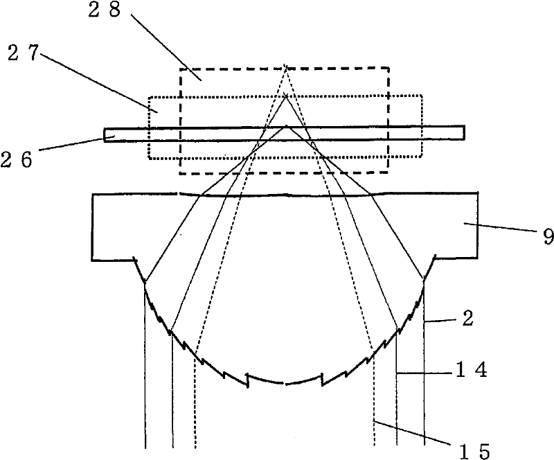
[0163] exist Figure 12 Among them, the optical disc 26 (or 27 , 28 , hereinafter the same) is placed on the turntable 182 and is rotationally driven by the motor 164 . The optical head device 155 shown in Embodiment 1 is roughly adjusted to the track position of the optical disc where desired information exists by the drive device 151 of the optical head device.
[0164] The optical head device 155 also sends a focus error (focus error) signal and a tracking error signal to the circuit 153 in accordance with the positional relationship with the optical disc 26 . The circuit 153 sends a signal for finely moving the objective lens to the optical head device 155 in response to the signal. Based on this signal, the optical head device 155 p...
PUM
| Property | Measurement | Unit |
|---|---|---|
| diameter | aaaaa | aaaaa |
Abstract
Description
Claims
Application Information
 - R&D
- Intellectual Property
- Life Sciences
- Materials
- Tech Scout
- Unparalleled Data Quality
- Higher Quality Content
- 60% Fewer Hallucinations
Browse by: Latest US Patents, China's latest patents, Technical Efficacy Thesaurus, Application Domain, Technology Topic, Popular Technical Reports.
© 2025 PatSnap. All rights reserved.Legal|Privacy policy|Modern Slavery Act Transparency Statement|Sitemap|About US| Contact US: help@patsnap.com


