Gasification furnace and charge-in system

A feeding system and gasifier technology, applied in the direction of granular/powdered fuel gasification, combined combustion mitigation, etc., can solve the problems of the feeding system that needs to be improved, no obvious changes, and difficult to detect, so as to improve safety and Operating time, preventing instability and temperature changes, increasing safety effects

Active Publication Date: 2009-07-29
IND TECH RES INST
View PDF2 Cites 6 Cited by
  • Summary
  • Abstract
  • Description
  • Claims
  • Application Information

AI Technical Summary

Problems solved by technology

[0006] Because coal gasification is generally carried out in a severe environment of high temperature and high pressure, it is necessary to be very careful in operation to avoid fusing due to external factors and internal fuel blockage at the outlet of the feed burner 26. Further, high-temperature tempering occurs. At this time, under the three conditions of fuel (coal), oxidant (oxygen) and high-temperature environment, the combustion reaction is directly carried out inside the feed burner 26, and the high temperature directly erodes the feed combustion. The relatively low-temperature-resistant insulation layer 22 or the refractory mud of the insulation layer 23 around the device 26 is quite difficult to detect because the fuel and oxidant are still continuously fed, and the furnace temperature does not change significantly. In the end, it may be that the gasifier wall 25 cannot withstand high temperatures, which pose a great danger
Therefore, the feeding system of the known gasifier still has deficiencies and needs to be improved.

Method used


Image

  • Gasification furnace and charge-in system
  • Gasification furnace and charge-in system
  • Gasification furnace and charge-in system

Examples


Embodiment Construction

[0056] Although the present invention will be fully described with reference to the accompanying drawings containing preferred embodiments of the present invention, it should be understood that those skilled in the art can modify the invention described herein while obtaining the effects of the present invention. Therefore, it should be understood that the following description is an extensive disclosure for those skilled in the art, and its content is not intended to limit the present invention.

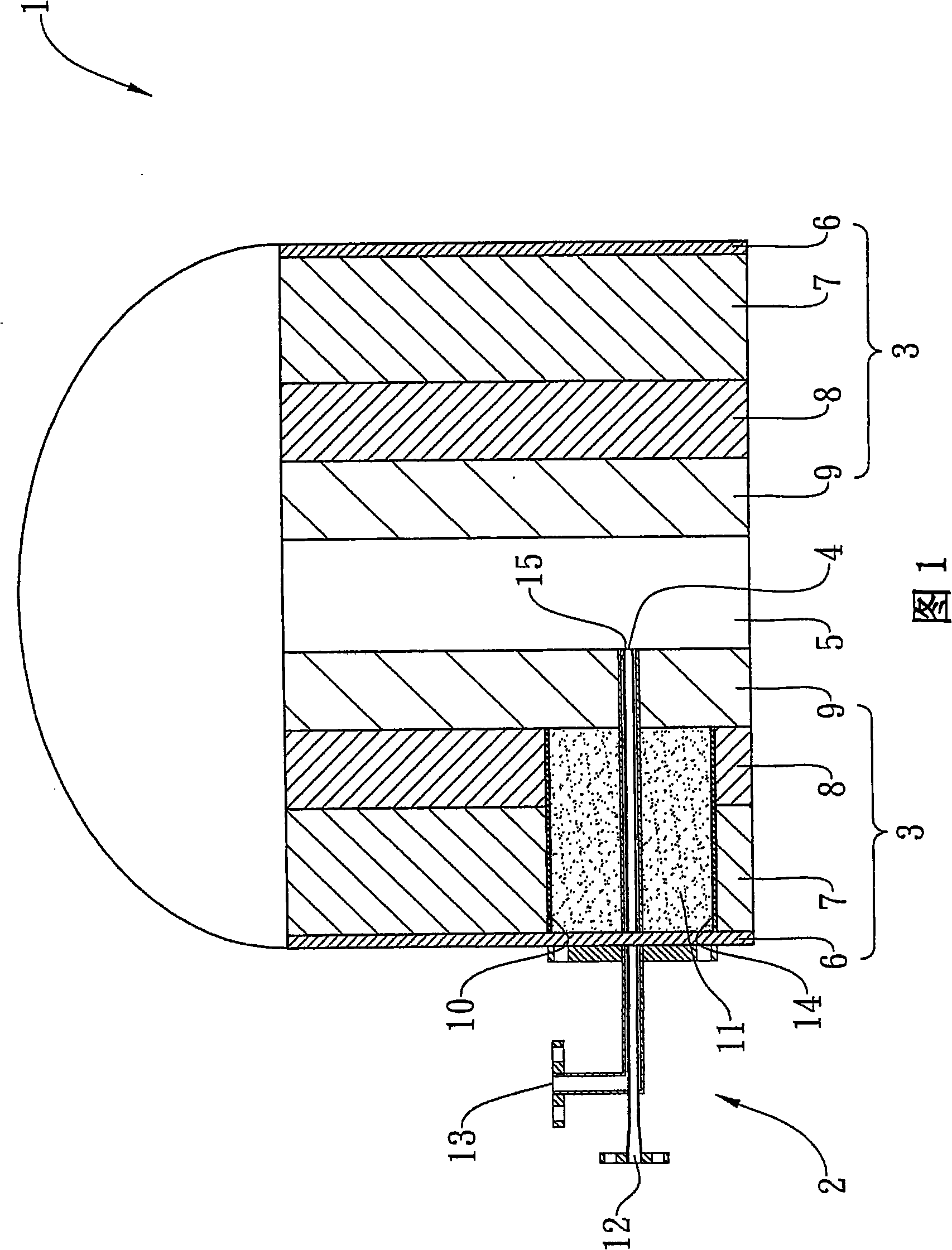
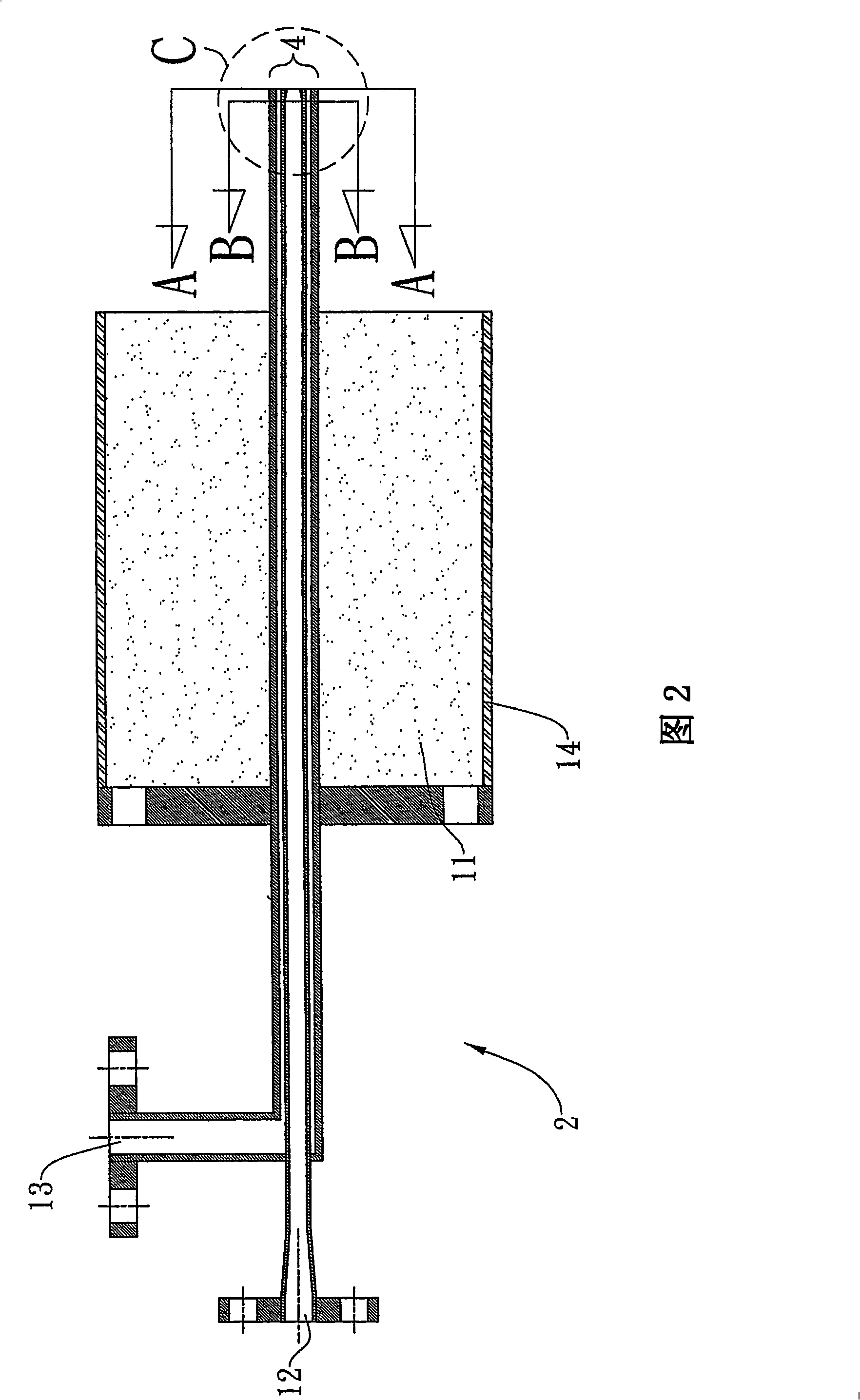
[0057] Please refer to FIG. 1, which shows a cross-sectional view of a first embodiment of a high-temperature gasification furnace 1 of the present invention. In this embodiment, the high-temperature gasification furnace 1 of the present invention includes a feed burner 2 and a gasification furnace body 3. The discharge port 4 of the feed burner 2 is connected to a gasification furnace core reaction zone 5, and the inlet The inlet (not shown) of the material burner 2 is connected to the...


PUM


Abstract

The invention discloses a gasification furnace and a feeding system thereof; wherein the gasification furnace comprises a feeding combustor and a gasification furnace, the discharge port of the feeding combustor is communicated with the reaction zone of a gasification furnace core, the feeding port of the feeding combustor is communicated with the outside of the gasification furnace, and the feeding combustor respectively and sequentially passes through the wall of the gasification furnace, the heat insulating layer, the insulating layer and the high temperature resistance layer from the outside of the gasification furnace and finally reaches the reaction zone of the gasification furnace core; the system is characterized in that high temperature resistance material is wrapped around the feeding combustor and respectively and sequentially passes through the heat insulating layer to the insulating layer from the wall of the gasification furnace. The invention can effectively prevent intense mobility caused by instability and temperature variation during gasification, enhance the security of integrated operation and running period, and improve the gasification efficiency.

Description

Technical field [0001] The present invention relates to a gasification furnace and its feeding system, in particular to a high-temperature gasification furnace and its feeding system that convey pulverized coal and conveying gas through the combination of an application mechanism of different refractory materials and a feed burner. Background technique [0002] In recent years, as the world faces environmental and energy issues at the same time, governments and industries in various countries have attached great importance to the research and development of clean coal technology with high energy efficiency and low pollution. How to improve the efficiency of coal use and reduce coal pollution is the primary topic of the current development of clean coal technology. Among various coal purification technologies, the gasification technique has attracted the most attention. It can use various fuels such as coal, petroleum coke, biomass, and waste as feedstock, and produce syngas (syng...

Claims


Application Information

Patent Timeline
Patent Type & Authority Applications(China)
IPC IPC(8): C10J3/48
CPCY02E20/18
Inventor 沈政宪许品超徐恒文陈美燕
Owner IND TECH RES INST
Why Eureka
Try Eureka