

Current detection circuit, current detection method, readable storage medium and power electronic equipment
A current detection circuit and current technology, applied in the direction of RMS measurement, etc., can solve the problems of the production process of rectifier diode voltage loss, increase the detection error of the current detection circuit, and cannot detect the fluctuating current, so as to reduce the risk of fusing or electrical fire. possibility, improve response speed, and reduce the effect of security risks
- Summary
- Abstract
- Description
- Claims
- Application Information
AI Technical Summary
Problems solved by technology
Method used
Image

Examples
Embodiment 11
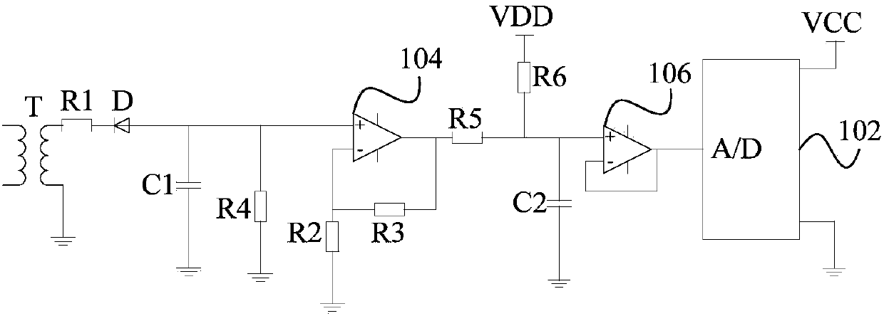
[0055] figure 1 A schematic diagram of a current detection circuit according to an embodiment of the present invention is shown.
[0056] Such as figure 1 As shown, the current detection circuit according to the embodiment of the present invention includes: a current mutual inductance component, which is connected to a strong current signal to be detected, and converts the strong current signal into a weak voltage signal and then outputs it; the control module 102 is connected to The output terminal of the current mutual inductance component is used for integral calculation of the weak current voltage signal, and the result of the integral operation is recorded as the voltage effective value, and the strong current signal is determined according to the magnitude relationship between the voltage effective value and the preset voltage effective value Whether it is an overcurrent signal.
[0057] In this technical solution, the strong current signal is converted into a weak cur...
Embodiment 12
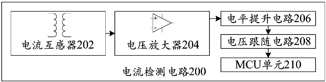
[0084] figure 2 A schematic block diagram of a current detection circuit 200 according to an embodiment of the present invention is shown.
[0085] Such as figure 2 As shown, the schematic block diagram of the current detection circuit 200 according to an embodiment of the present invention includes: a current transformer 202, whose input winding coil is connected to the bus line of the strong current signal, and is used to convert the strong current signal into a weak current signal, and then convert the weak current signal into a voltage signal; the input terminal of the voltage amplifier 204 is connected to the output terminal of the current transformer 202, and is used to receive the voltage signal output by the current transformer 202, and scale the voltage signal; Lifting circuit 206, the input end is connected to the output end of the voltage amplifier 204, is used for carrying out the boost processing to the voltage signal after scaling; The processed voltage signa...
Embodiment 13
[0097] Figure 7 A schematic flowchart of a current detection method according to an embodiment of the present invention is shown.
[0098] Such as Figure 7 As shown, the current detection method according to an embodiment of the present invention includes: step S702, within a preset time period, access the strong current signal to be detected, and convert the strong current signal into a weak voltage signal and output it; Step S704, perform integral calculation on the weak current voltage signal, and record the result of the integral calculation as the voltage effective value; Step S706, determine whether the strong current current signal is an overcurrent according to the magnitude relationship between the voltage effective value and the preset voltage effective value Signal.
[0099] In this technical solution, by converting the strong current signal into a weak current voltage signal, the hardware requirements of the current detection circuit are reduced, and the effect...
PUM
 Abstract
Description
Claims
Application Information