Vertical rotor type gas electromagnetic valve

一种燃气电磁阀、转子式的技术,应用在阀细节、阀装置、阀的操作/释放装置等方向,能够解决转子与定子精确定位定子结构加工难度及成本高、未考虑到调节、未考虑到磁路长度等问题,达到有效绕组周长减少、漆包线及导磁材料用量减少、节省材料的效果

Inactive Publication Date: 2009-07-29
潘兆铿
View PDF2 Cites 13 Cited by
  • Summary
  • Abstract
  • Description
  • Claims
  • Application Information

AI Technical Summary

Problems solved by technology

Obviously, the above-mentioned vertical rotor electromagnet does not take into account the influence of the length of the magnetic circuit on the effect of electromagnetic action, nor does it take into account the adjustment of the relationship curve between the magnetic force and the rotor stroke and current, and how to accurately position the concentricity of the rotor and the stator And factors such as processing difficulty and high cost of the stator structure in mass production

Method used


Image

  • Vertical rotor type gas electromagnetic valve
  • Vertical rotor type gas electromagnetic valve
  • Vertical rotor type gas electromagnetic valve

Examples


Embodiment 1

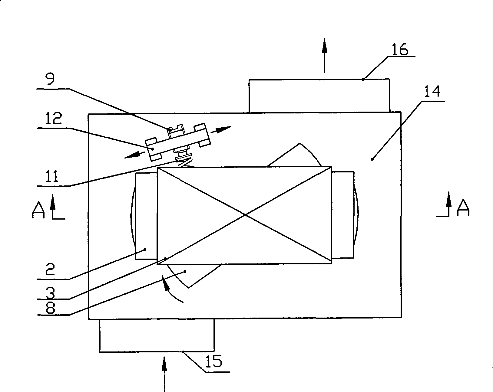
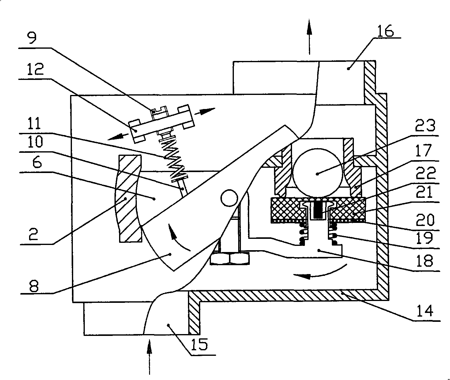
[0025] see figure 1 , figure 2 , Fig. 3 can be seen, a kind of vertical rotor type gas electromagnetic valve is installed on the vertical rotor type electromagnet, valve housing 14, adjustment spring 11, adjustment nail 10, rotor adjustment screw 9, adjustment screw bracket 12, swing arm 18 and The rubber gasket assembly at the outer end of the swing arm 18 is composed, and the valve housing 14 is provided with an air inlet 15 , an air outlet 16 and a valve port 17 . The vertical rotor electromagnet consists of coil winding 3, stator core 1, stator side piece 2, rotor 8, upper rotor fixing piece 4, and lower rotor fixing piece 5. The rotor 8 is long and has front and rear Symmetrical outer arc.

[0026] The rotor shaft 7 of the vertical rotor type electromagnet is located on the center line of the stator core 1, the upper and lower rotor fixing pieces 4 and 5 are at an angle of 90° to the rotor shaft, and the upper rotor fixing piece 4 is located on the upper side of the ro...

Embodiment 2

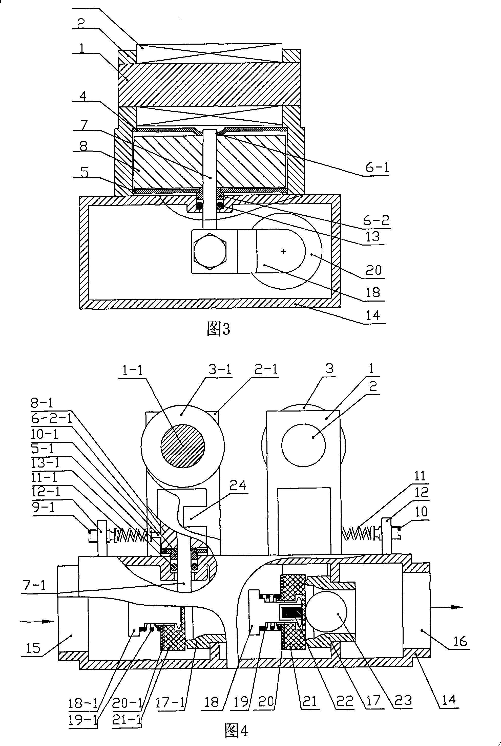
[0034] Referring to Fig. 4, the present embodiment is a double-enclosed gas flow regulating valve composed of two vertical rotor type gas solenoid valves, one of which is used as a gas regulating valve, which is the same as in Embodiment 1. And the other is used for gas opening and closing alone, its structure is the same as the main body structure described in embodiment 1, the difference is that it is provided with boss 24 on the inner arc surface of a stator side piece 2-1, and cancels A permanent magnet 22 and a magnetic permeability adjustment block 23 are provided. That is, in Fig. 4, the gas control valve is located on the right side, and the gas switching valve is located on the left side, which together form a gas control valve with double sealing effect. Stator iron core 1-1, stator side piece 2-1, coil winding 3-1, upper rotor fixing piece 4-1, lower rotor fixing piece 5-1, bearing boss 6-2- of the gas switching valve in Fig. 4 1. Rotor shaft 7-1, rotor 8-1, rotor ...


PUM


Abstract

The invention discloses a vertical rotor fuel gas solenoid valve, the structure of which can lead a magnetic circuit of the solenoid valve to be shortened and lead the processing technique to be simple, and the concentricity of a rotor and a stator has accurate location and convenient adjustment, and the relation curve of the fuel gas flow rate and current can be adjusted at any time, so the smallest starting point of the fuel gas flow rate can be determined and the adjustment and location are accurate; the solenoid valve can be used for adjusting the fuel gas flow rate and used as a switch, and the solenoid valve can be changed into a strong absorbing valve. The fuel gas solenoid valve comprises a vertical rotor electromagnet, a rotor adjusting bolt, a bracket, a spring and an adjusting bolt; a sealing gasket and a gasket spring are arranged on round lug boss at the external end of a swinging arm which is fixedly connected with a rotor shaft, and the round lug boss is connected with a valve port in a matching way for adjusting the fuel gas flow rate; the transverse positions of the rotor adjusting bolt and the bracket are adjusted for adjusting the relation curve of the fuel gas flow rate and the winding current, and the smallest starting point of the fuel gas flow rate can be determined.

Description

technical field [0001] The invention relates to the technical field of gas solenoid valves, in particular to a vertical rotor type gas solenoid valve. Background technique [0002] The rotor type solenoid valve uses the rotor type electromagnet as the driving element. The rotor type electromagnet uses its rotating shaft to fix the iron core of the rotor. The gap between the rotor iron core and the stator iron core can be small, but the shaft and the bearing will produce Frictional force, since the diameter of the rotating shaft is much smaller than that of the rotor, the frictional force is much smaller than the frictional force generated by the direct contact between the spool and the solenoid wall of the solenoid electromagnet. The initial suction force of the rotor type electromagnet is large, which just meets the requirements of overcoming the back pressure and the viscous force between the valve port and the rubber seal when the gas solenoid valve is opened. The charac...

Claims


Application Information

Patent Timeline
Patent Type & Authority Applications(China)
IPC IPC(8): F16K31/06
CPCF16K31/0682
Inventor 潘兆铿
Owner 潘兆铿
Why Eureka
Try Eureka