
Method of grinding an indexable insert and grinding wheel for carrying out the grinding method

A technology of indexing blades and rotating grinding wheels, which is applied to tools used in lathes, parts of grinding machine tools, and tools used in planer/slotting machines, etc. It can solve problems such as wired contact, reduce wear of grinding wheels, and improve cooling conditions , the effect of simple structure

Inactive Publication Date: 2009-07-29
ERWIN JUNKER MASCHNINENFAB
View PDF3 Cites 11 Cited by
  • Summary
  • Abstract
  • Description
  • Claims
  • Application Information

AI Technical Summary

Problems solved by technology

In addition, the clamped indexable insert only allows deflection movement on the tool holder with at least a wire contact
This type of grinding cannot be compared to cost-effective grinding methods used in mass production of indexable inserts

Method used


Image

  • Method of grinding an indexable insert and grinding wheel for carrying out the grinding method
  • Method of grinding an indexable insert and grinding wheel for carrying out the grinding method
  • Method of grinding an indexable insert and grinding wheel for carrying out the grinding method

Examples


Embodiment Construction

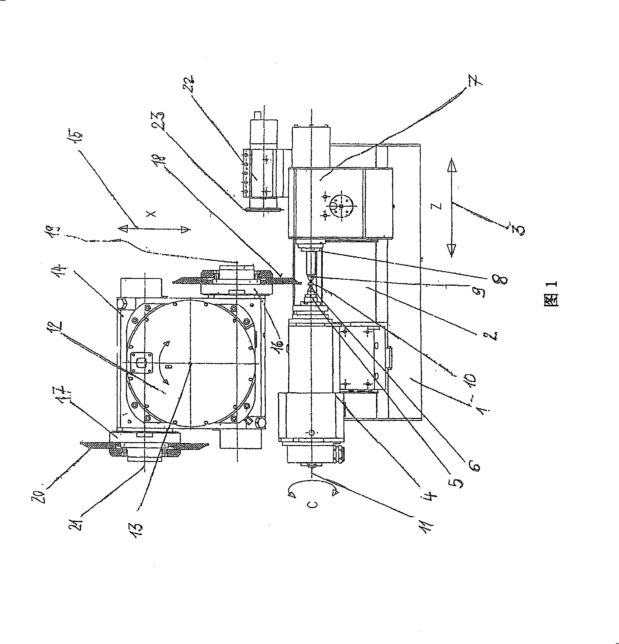
[0039] Figure 1 shows a schematic top view of the grinding machine, which conforms to the structure of a universal circumferential grinding machine and a non-circumferential grinding machine. Most of the parts of the grinder are included in the picture. The table 2 on the bed 1 can move along the first moving axis 3 . The movement axis 3 is generally referred to as the Z-axis in the construction of grinding machines. A head frame 4 with a clamping device 5 and a plug-in clamp 6 is mounted on the workbench 2 . There is a tailstock 7 with a centering clamp 8 and a locking bolt 9 at a certain distance from the headstock 4 . The headstock 4 and the tailstock 7 generally can move towards or in the same direction. The indexable insert 10 can be fixed and centered with a plug-in fixture 6 and clamped with a tailstock 7 and a locking bolt 9 .

[0040] The indexable insert 10 can be driven to rotate by the head frame 4 . During the grinding process, the indexable insert 10 rotates...


PUM


Abstract

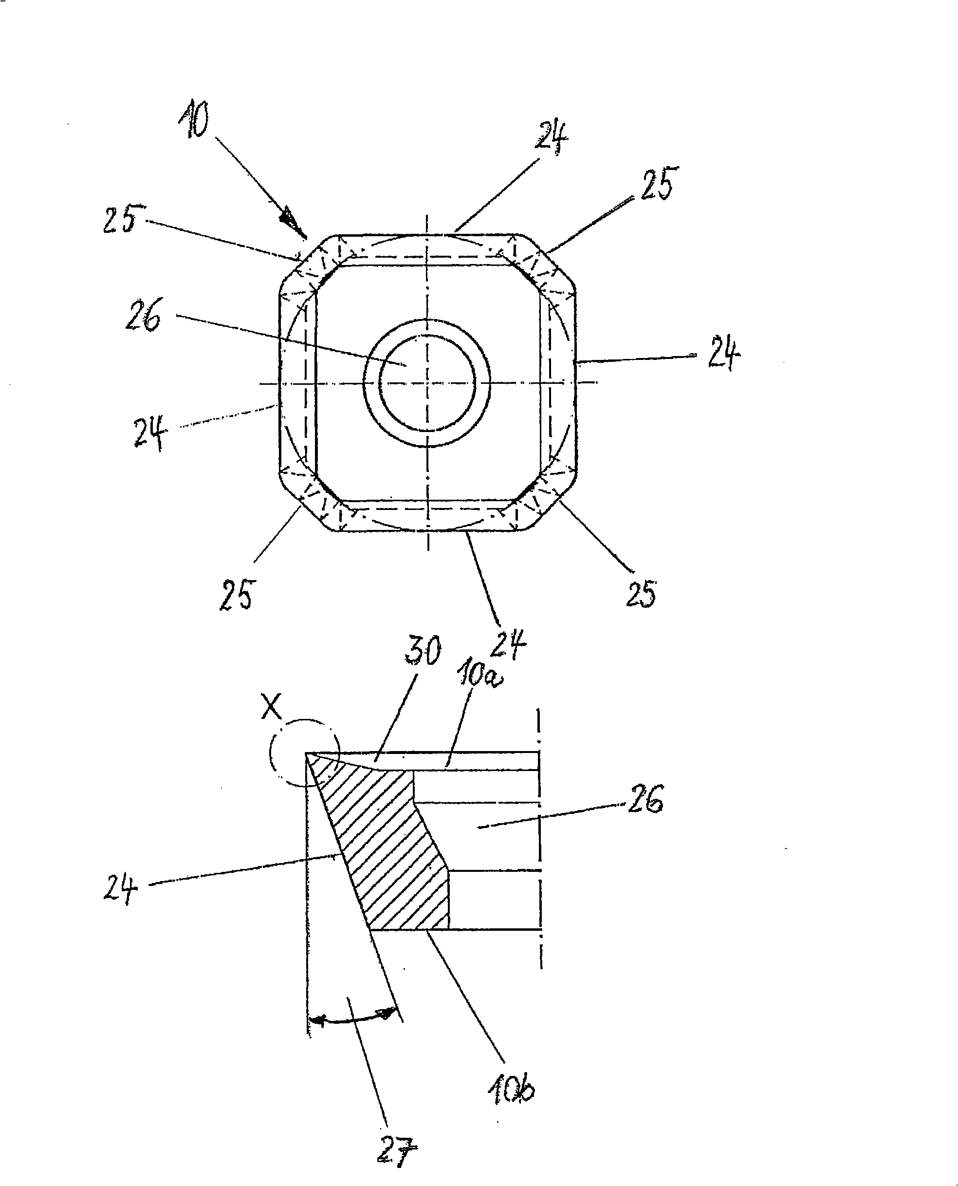
In an indexable insert having the wide sides 10a, 10b, the inclined narrow sides 24 are to be ground, that is to say the grinding allowance 38 is to be removed. To this end, the indexable insert 10 is set in rotation about the driven axis of rotation 11 (C axis) between a clamping insert 6 and a thrust bolt 9. Serving for the grinding is a grinding wheel 18 which rotates about the rotation axis 19 and which has a circumferential surface 18a contoured in a circular shape and having the largest diameter 43 and is composed of a leading region 41 and a trailing region 42. The grinding wheel 18 is guided relative to the indexable insert 10 along the geometrical defining line 39 which is formed by the generating line of the finished narrow side 24 in the feed direction 44. The leading region 41 tapering forwards effects preliminary grinding of the narrow side 24 by longitudinal grinding, whereas the trailing region 42 effects finish grinding by linear contact with the narrow side 24. The grinding wheel 18 is held with the clamping flanges 40 on a grinding spindle. The grinding operation is effected with controlled movement of the driven axis of rotation 11 (C axis), a first displacement axis 3 (Z axis), a second displacement axis 15 (X axis) and a pivoting movement of the grinding wheel 18 relative to the indexable insert 10 according to double arrow B.

Description

technical field [0001] The invention relates to a method for grinding indexable inserts according to the preambles of claims 1 to 3, wherein the narrow edge of the insert is moved along and ground by an annular contoured peripheral surface of a rotating grinding surface , the grinding process is performed through the following coordinated CNC movements: [0002] a) The indexable insert is driven to rotate around a shaft perpendicular to the blade face; [0003] b) A grinding wheel shaft equipped with a grinding wheel and driving the grinding wheel moves relative to the rotating shaft of the indexable blade along two mutually perpendicular moving axes, and the two moving axes are located in two parallel planes or the same plane. [0004] c) The grinding wheel shaft and the indexable blade move relative to each other around a rotating shaft, and the rotating shaft is perpendicular to the plane where the moving shaft and the rotating shaft of the indexable blade are located, B...

Claims


Application Information

Patent Timeline
Patent Type & Authority Applications(China)
IPC IPC(8): B24B3/34
CPCB24B3/343B24B3/34B24B49/00B24D3/10
Inventor 胡贝特·米勒
Owner ERWIN JUNKER MASCHNINENFAB
Learn More