Light source comprising a saturated colour appearance

A light source, light color technology, applied in the field of fluorescent lamps, can solve the problems of discomfort, low heat resistance of filter film, inability to color saturation and other problems

Inactive Publication Date: 2009-07-29
OSRAM GMBH
View PDF0 Cites 0 Cited by
  • Summary
  • Abstract
  • Description
  • Claims
  • Application Information

AI Technical Summary

Problems solved by technology

Although this solution enables improved color saturation, it is not suitable for high-load lamp types (lamp currents greater than approx. 300 mA) due to the low heat resistance of the filter membrane
Known high-temperature resistant plastics such as tetrafluoroethylene-hexafluoropropylene copolymer (FEP) or polyamide (PA) cannot be colored properly to improve color saturation, or have an inherent color that is too strong for this color application

Method used


Image

  • Light source comprising a saturated colour appearance

Examples


Embodiment Construction

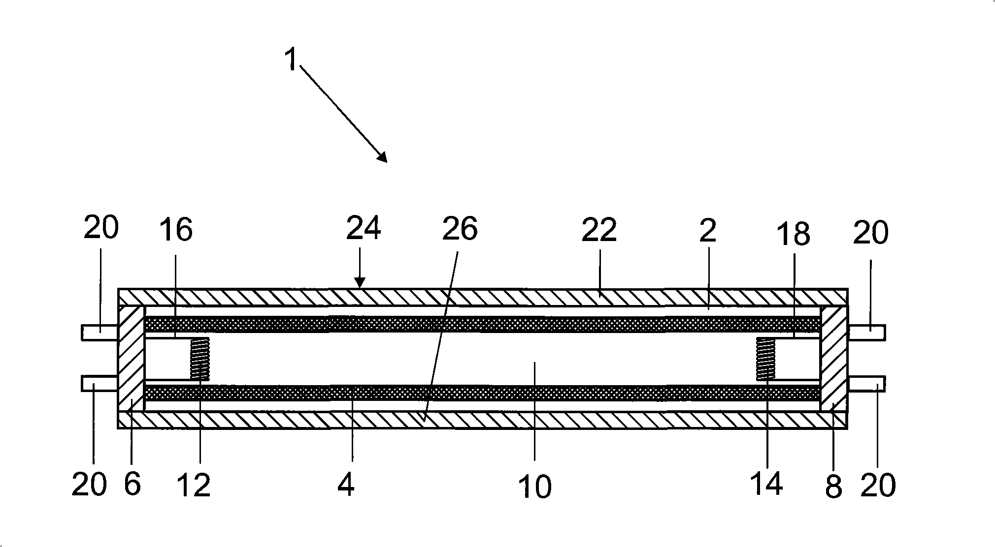
[0015] figure 1 A schematic diagram of a light source according to the invention embodied as a fluorescent lamp 1 is shown. The light source has, for example, a rod-shaped or tubular lamp vessel 2 made of glass, which is provided with a phosphor layer 4 . The lamp vessel 2 has an inner space 10 sealed on both sides by cap parts 6 , 8 , into which two diametrically opposed electrodes 12 , 14 (incandescent filaments) protrude, between which a gas forms during lamp operation. discharge. The electrodes 12, 14 are connected for electrical contact via feeders 16, 18 respectively to contact rods 20, which pass through the base parts 6, 8 and are connected to corresponding sockets (not shown) of the illuminants to enable Stable mechanical holding and reliable electrical contacting of the fluorescent lamp 1 . An ionizable filling, which essentially consists of one or more noble gases and a small amount of mercury, is contained in the interior 10 of the lamp vessel 2 . High temperat...


PUM


Abstract

The invention relates to a light source, especially a fluorescent lamp, comprising at least one bulb, a silicon rubber which is resistant to high temperatures being arranged on the bulb. Said silicon rubber is provided with at least one pigment influencing the colour appearance and light saturation in order to generate a saturated colour appearance.

Description

technical field [0001] The invention relates to a light source, in particular a fluorescent lamp, which has at least one lamp vessel. Background technique [0002] It is known from the general prior art to arrange a corresponding pigment sublayer as a color filter between the lamp vessel and the phosphor layer for generating a spectrum in different color ranges. These pigment underlayers absorb undesired parts of the lamp's spectrum so that the desired chromaticity coordinates are achieved, for example in NiSbTiO 2 Yellow chromaticity coordinates in the case of pigments or when using Fe 2 o 3 Chromaticity coordinates of red in the case of pigments. Disadvantages in such light sources are that, on the one hand, the pigment base absorbs a large part of the light radiation, thereby reducing the efficiency of the fluorescent lamp, and that, on the other hand, the coating process for producing the pigment base is complex and expensive. Furthermore, it has been found that the ...

Claims


Application Information

Patent Timeline
Patent Type & Authority Applications(China)
IPC IPC(8): H01J61/40F21V25/12
CPCH01J61/40
Inventor 阿明·康拉德斯特凡·阿佩尔
Owner OSRAM GMBH
Why Eureka
Try Eureka