External cowling of scramjet engine and design method thereof

A scramjet and external rectification technology, applied in aircraft parts, aircraft power units, aircraft power unit components, etc., can solve the problems of improving and affecting the lift-to-drag ratio of the aircraft, unfavorable to the lift-drag ratio of the aircraft, and reduce the headwind. Area, good aerodynamic performance, the effect of reducing drag

Inactive Publication Date: 2009-08-05
INST OF MECHANICS - CHINESE ACAD OF SCI
View PDF0 Cites 12 Cited by
  • Summary
  • Abstract
  • Description
  • Claims
  • Application Information

AI Technical Summary

Problems solved by technology

However, the outer fairing of the engine generally adopts a conventional planar plan, which affects the lift-t

Method used


Image

  • External cowling of scramjet engine and design method thereof
  • External cowling of scramjet engine and design method thereof
  • External cowling of scramjet engine and design method thereof

Examples


Embodiment 1

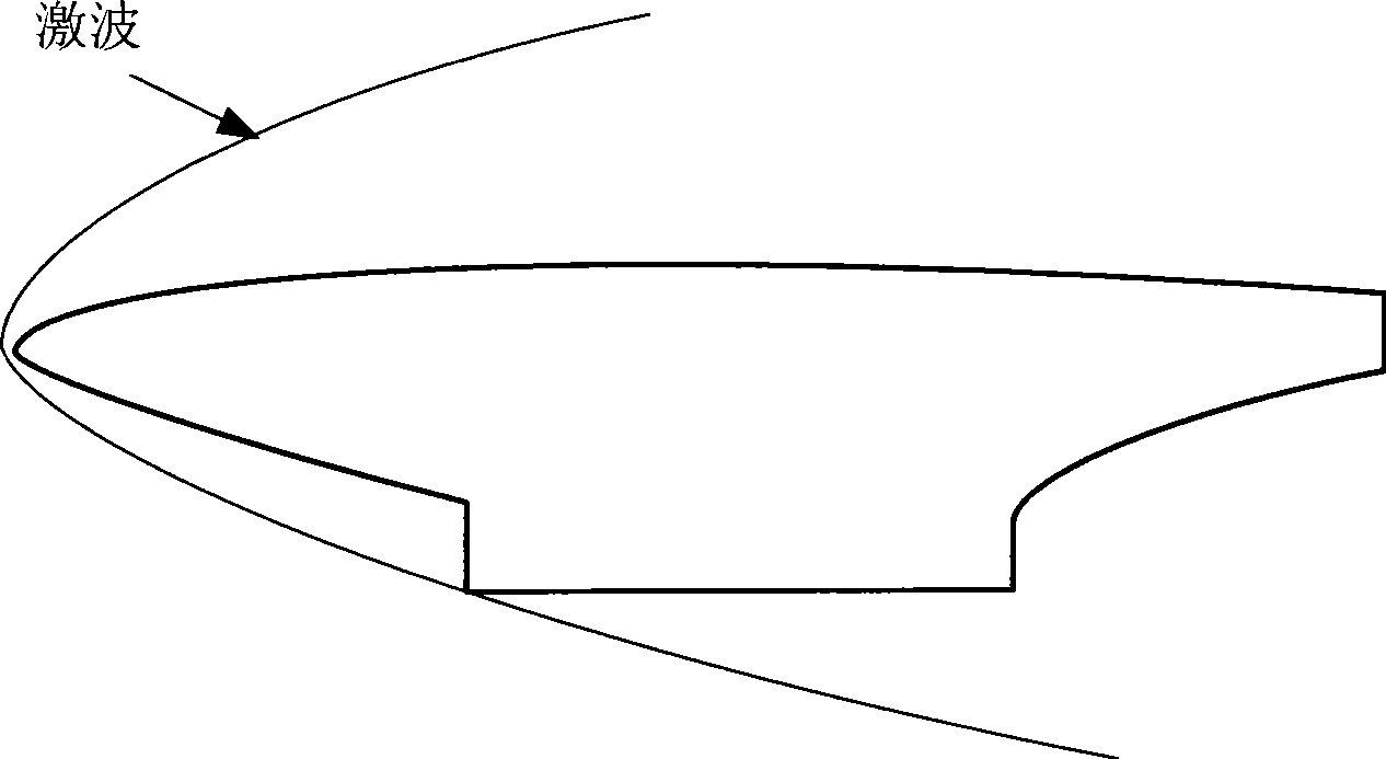
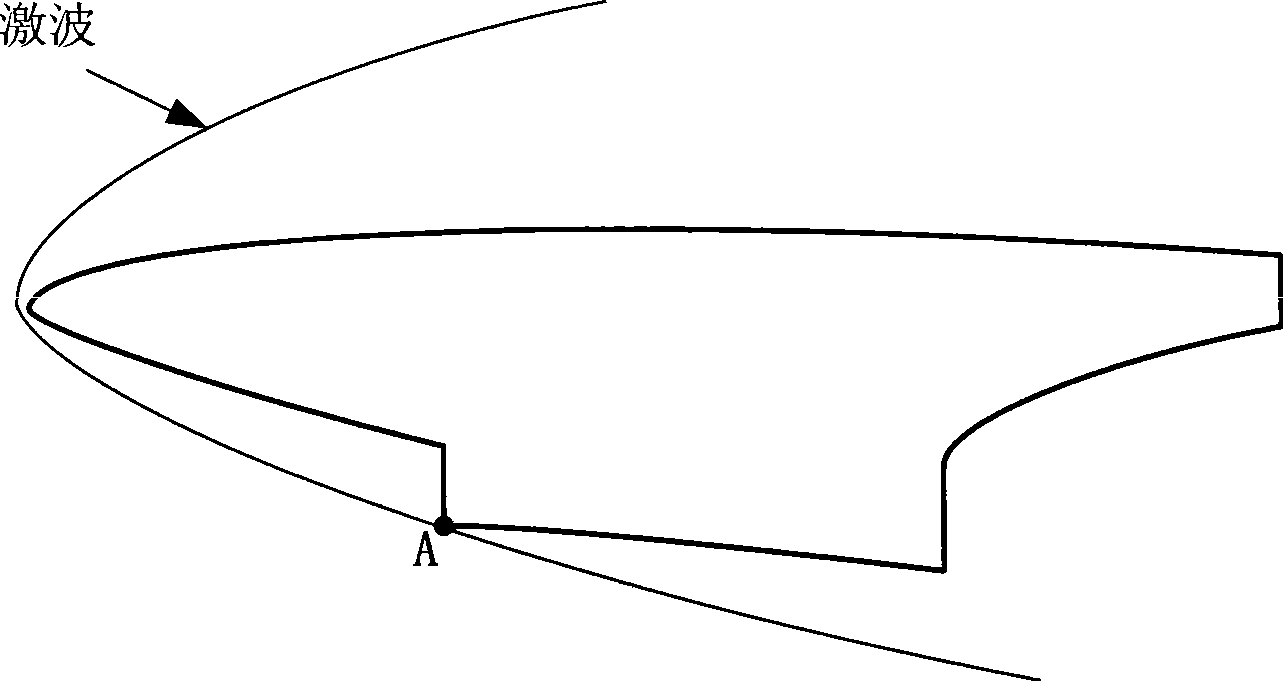
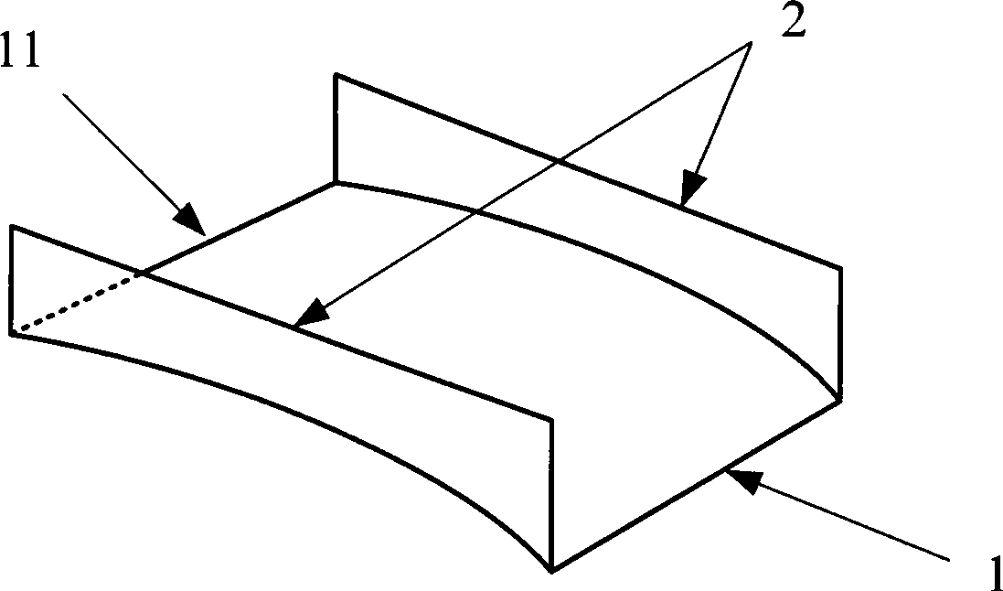
[0025] Such as Figure 1a with 1b The two-dimensional schematic diagram of the hypersonic vehicle shown. The entire aircraft can be divided into three main parts: the front body, the engine and the rear body. In the existing design, the outer fairing part of the engine adopts Figure 1a In the common fairing design scheme, the outer fairing of the present invention is as Figure 1b with figure 2 As shown, it includes a side plate 2 and a bottom plate 1, the bottom plate 1 is a rectangular plate, and protrudes upwards to form an arc-shaped cover, which is formed by protruding along the direction of the lip 11 of the bottom plate to the opposite side of the lip 11, and the front of the aircraft The high-pressure area generated by the body-induced shock wave is basically wrapped under the lower wall of the arc-shaped cover formed by the bottom plate 1, so the high-pressure area behind the shock wave can generate additional lift for the aircraft, and the two side plates 2 are a...

Embodiment 2

[0027] The design method of scramjet outer fairing of the present invention, concrete steps are:

[0028] 1) Under the condition of hypersonic flight, first conduct an inviscid analysis on the flow field of the aircraft to obtain detailed data of the flow field and the exact position of the shock wave;

[0029] 2) Starting from the lip of the engine inlet, follow the streamline equation along the incoming flow direction, and the curved surface formed by all the streamlines constitutes the lower wall of the engine outer fairing bottom plate;

[0030] 3) The two side plates of the outer fairing are relatively arranged on the bottom plate, and the side wall surface of the side plate can be a plane perpendicular to the lower wall surface of the bottom plate;

[0031] 4) According to the incoming flow conditions, deflect the outer fairing counterclockwise along point A of the lip (see Figure 1b ), the specific deflection angle can be obtained by calculation or experiment accordin...


PUM


Abstract

The invention discloses an outer rectifying cover of a scramjet engine and a method for designing the same. The main design thought comprises the following steps: firstly carrying out non-adhesion numerical analysis on a flow field generated on a front body of a hypersonic speed aerocraft; then designing the lower wall face shape of the outer rectifying cover in the flow field in a flown line tracing mode, and adopting a plane vertical to the lower wall on the side wall of the outer rectifying cover; and deflecting the outer rectifying cover by certain angle to obtain the outer rectifying cover of the scramjet engine according to the information such as flight attack angle, flight mach number and the like of the aerocraft by taking the lip opening position of the outer rectifying cover asa rotating point. The outer rectifying cover of the scramjet engine adopts the design principle of a waverider body, makes full use of a high pressure area after shocking waves to generate additionallift force, and reduces incident flow area and pressure difference resistance by deflecting the rectifying cover to make the whole aerodynamic performance of the aerocraft obviously improved. The outer rectifying cover can be directly applied to designing the hypersonic speed aerocraft taking various scramjet engines as power.

Description

technical field [0001] The invention relates to a technology of hypersonic vehicle configuration design with a scramjet engine as a power system, and in particular relates to an airframe / engine integrated configuration design in pursuit of the aerodynamic performance of the aircraft. Background technique [0002] A hypersonic vehicle is one that travels in the atmosphere and across the atmosphere at speeds of Mach 5 or higher. When the aircraft flies at hypersonic speed, the wave resistance and frictional resistance increase sharply, which leads to the increase of aerodynamic resistance and the decrease of engine thrust margin, resulting in a serious thrust-drag matching problem. In order to reduce drag and increase lift, and ensure the overall performance of the aircraft, the fuselage and engine are generally designed with a high degree of integration, that is, the front of the fuselage is integrated with the engine inlet, and the rear of the fuselage is integrated with the...

Claims


Application Information

Patent Timeline
IPC IPC(8): B64D29/00
Inventor 崔凯杨国伟
Owner INST OF MECHANICS - CHINESE ACAD OF SCI
Why Eureka
Try Eureka