Greening combined building block, and greening wall and greening cylinder made thereof

A block and column technology, applied to walls, noise absorbing devices, botanical equipment and methods, etc., can solve the problems of no greening on walls or columns, no greening effect, waste of land resources, etc., and achieve greening effect Good, simple structure, beautify the environment

Inactive Publication Date: 2009-08-05
孙希贤
View PDF1 Cites 6 Cited by
  • Summary
  • Abstract
  • Description
  • Claims
  • Application Information

AI Technical Summary

Problems solved by technology

[0002] The traditional wall or column has no greening, or creepers are often used for greening, or tall plants are planted to block the greening; roads are separated by steel structures, cement piers or green belts; both sides of the railway are separated by barbed wire and fences. Disadvantages No greening effect, or waste of land resources
The ecological block o...

Method used


Image

  • Greening combined building block, and greening wall and greening cylinder made thereof
  • Greening combined building block, and greening wall and greening cylinder made thereof
  • Greening combined building block, and greening wall and greening cylinder made thereof

Examples


example 1

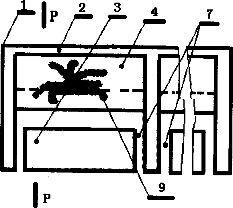
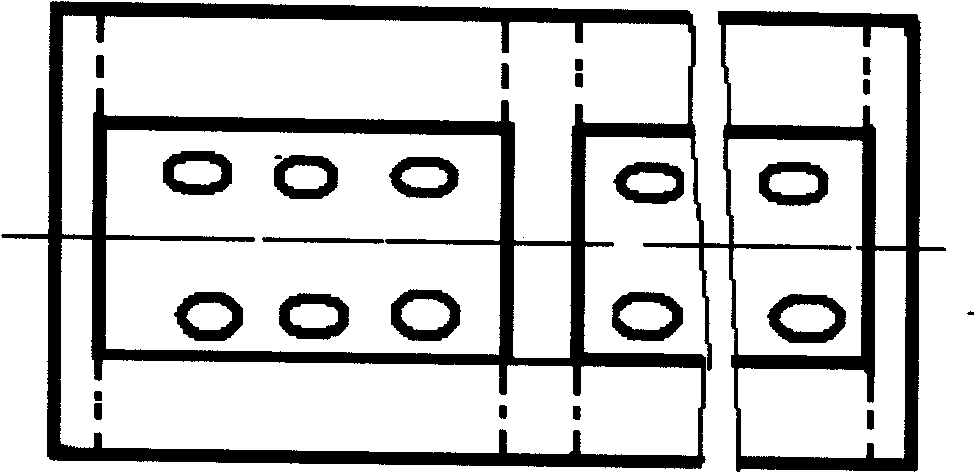
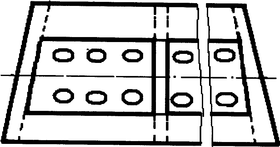
[0083] Example 1: see figure 1 , figure 2 , Figure 5 , Figure 13 , Figure 14 , Figure 19 In this example, one of the base material cement mortar, slag powder, building slag powder, rock powder, and plastic is used to form a mold, or clay is molded and fired to form block 2 and block 3 , the block 2 is built on the foundation, the block 3 is placed in the lower part of the cavity of the block 2, and the block 2 and the block 3 are bonded at the connection port 7 with cement, that is, a hollow planting hole 4 and a concave shape are formed inside. Cavity 5, water supply and drainage holes 6 double-sided planting and greening combination block 1 (i.e. double-sided planting and greening combination block 1 with bottom V-shaped hollow planting hole), and the greening combination block 1 is built into a wall , the water source is connected with the water supply and drainage hole 6 of the uppermost composite block, and the water will naturally flow from top to bottom from t...

example 2

[0084] Example 2: See figure 1 , figure 2 , Image 6 , Figure 13 , Figure 14 , Figure 20 , Example 2 is basically the same as Example 1, except that block 2 and block 3 form a double-sided planting greening combination block 1 with no bottom V-shaped hollow planting hole.

example 3

[0085] Example 3: See figure 1 , figure 2 , Figure 7 , Figure 13 , Figure 15 , Figure 21 , Example 3 is basically the same as Example 1, except that block 2 and block 3 form a double-sided planting greening combination block 1 with a circular arc-shaped hollow planting hole at the bottom.


PUM


Abstract

The invention relates to a virescence facility, in particular to a virescence combination building block on which flowers and plants are planted, and a virescence wall body and a virescence column body which are made of the combination building blocks. The virescence facility comprises the virescence combination building blocks (1), building blocks (2), building blocks (3), hollow planting holes (4), concave hollow spaces (5), water supply and drain holes (6), connecting openings (7), soil (8), flowers and plants (9), water supply and drain holes (10), planting surfaces (11), the virescence wall bodies and the virescence column bodies (12). The manufactured building block (2) and the building block (3) are combined and cemented by cement at connecting openings (7), the virescence combination building block (1) with the hollow planting holes (4), the water supply and drain holes (6), the water supply and drain holes (10) and the planting surfaces (11) can be manufactured, then the virescence combination building blocks are piled up to form the virescence wall body or the virescence column body, the soil (8) is put into the hollow planting holes (4), and the flowers and plants (9) are planted. The invention has the advantages of simple structure, low cost and good virescence effect.

Description

technical field [0001] The invention relates to a greening facility, in particular to a greening composite block on which flowers and plants are planted and a greening wall and a greening column made of the composite block. Background technique [0002] The traditional wall or column has no greening, or creepers are often used for greening, or tall plants are planted to block the greening; roads are separated by steel structures, cement piers or green belts; both sides of the railway are separated by barbed wire and fences. The disadvantage is that there is no greening effect, or a waste of land resources. The ecological block of the patent CN2914640 can plant flowers and plants in the planting hole, and it must be attached to another wall to realize it. This kind of block can only be greened on one side, and the axis of the planting hole is parallel to the ground, and the inside is small and the outside is large. When it rains, it will wash away the flowers, grass and soil...

Claims


Application Information

Patent Timeline
IPC IPC(8): E01F8/02E04C1/39A01G9/02E04B2/02
CPCA01G31/001E04C1/395A01G9/104A01G9/0295A01G24/15A01G24/17A01G24/44
Inventor 孙希贤
Owner 孙希贤
Why Eureka
Try Eureka