Crankshaft case respiration apparatus of internal-combustion engine

A technology for internal combustion engine crankcases and breathing devices, which can be used in crankcase ventilation, mechanical equipment, engine components, etc. It can solve the problems of inability to generate pulsating pressure, unclear separation, and poor closing effect of float or reed check valves. problems, achieve the effect of reducing oil consumption and pollutant emissions, and reducing oil content

Inactive Publication Date: 2009-08-05
盐城兴动机械有限公司
View PDF10 Cites 15 Cited by
  • Summary
  • Abstract
  • Description
  • Claims
  • Application Information

AI Technical Summary

Problems solved by technology

However, because the floating ball of the floating ball respirator can only be placed vertically, it takes up a lot of space in the height direction, and the arrangement is inconvenient. Moreover, when the internal combustion engine stops, the evaporation of oil and gas in the crankcase can easily blow up the floating ball and cause oil and gas leakage.
However, due to the large contact area between the reed and the reed seat, the reed respirator is often unclear after sticking to the oil, the ventilation is not smooth, and the reed is easily deformed, the closing effect is poor, and it often fails.
What is more serious is that these respirators or breathing systems only directly discharge the crankcase gas into the atmosphere, causing air pollution and oil flow at the outlet of the respirator, which is why the ground is full of oil stains in the existing single-cylinder engine use
And, for multi-cylinder internal combustion engine, because the pressure in its crankcase is comparatively steady, can't produce the pulsating pressure that makes float type or reed type check valve open and close, makes existing float type or reed type check valve Ventilation devices are difficult to apply in multi-cylinder internal combustion engines

Method used


Image

  • Crankshaft case respiration apparatus of internal-combustion engine
  • Crankshaft case respiration apparatus of internal-combustion engine
  • Crankshaft case respiration apparatus of internal-combustion engine

Examples


Embodiment Construction

[0031] In order to enable those skilled in the art to better understand the solution of the present invention, the present invention will be further described in detail below with reference to the accompanying drawings and specific embodiments.

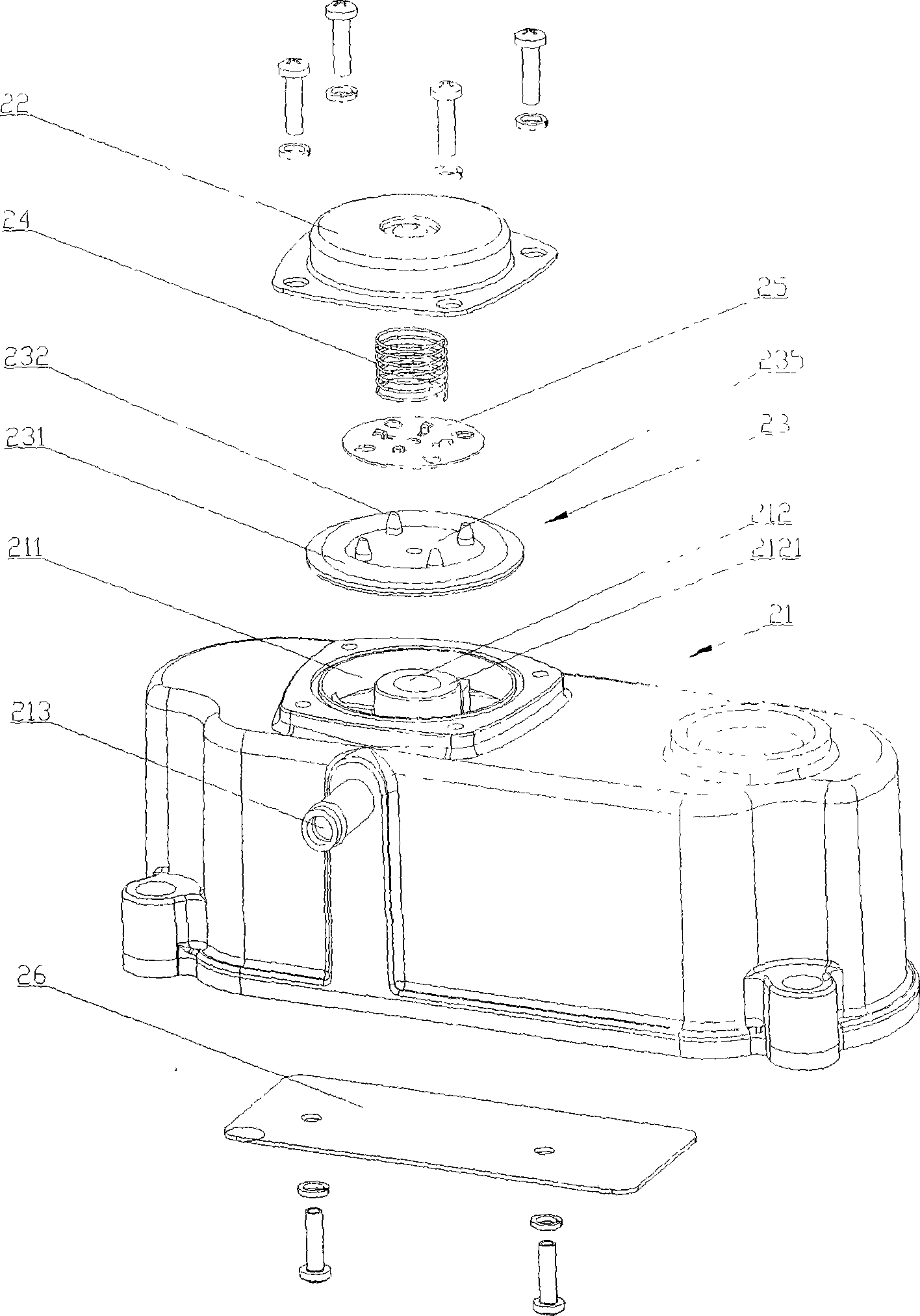
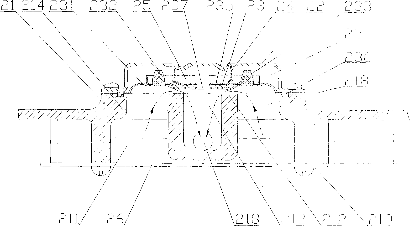
[0032] Please refer to figure 2 with Figure 5 , figure 2 It is a schematic structural diagram of a crankcase breathing device for an internal combustion engine provided by a specific embodiment of the present invention, Figure 5 for figure 2 The schematic diagram of the contour shape of the breathing cavity and the labyrinth cavity of the crankcase breathing device of the internal combustion engine shown.

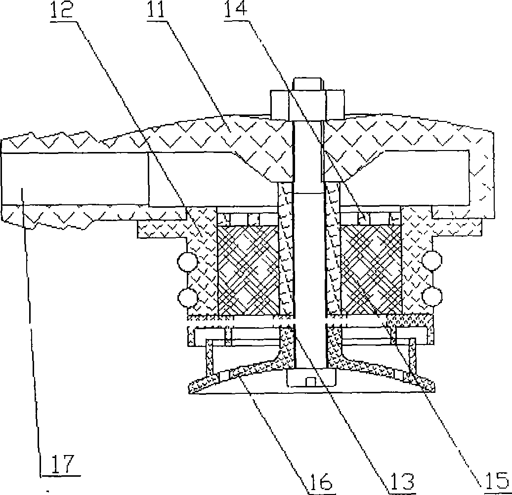
[0033] In a specific embodiment, the crankcase breathing device for an internal combustion engine provided by the present invention includes a housing 21. The side wall 214 of the housing 21 mostly encloses the contour of a closed breathing chamber 211, and a small part forms a right-angle circuitous arrangement. The labyrinth cav...


PUM


Abstract

The invention provides a crankcase respiration apparatus for an internal combustion engine, which adopts the structure that a shell is internally provided with a labyrinth cavity used for filtering oil drops and a respiratory cavity communicated with the labyrinth cavity, wherein the respiratory cavity is connected with a ventilating pipe for gas exhaust by a respiratory part; the respiratory part is a respiratory valve which comprises a respiratory membrane, a central pipe, a spring and a spring base plate, the respiratory membrane is provided with an elastic skirt rim, the middle of the respiratory membrane is provided with a balancing hole, and the bottom surface of the respiratory membrane is provided with a protrusion which corresponds the end surface of the central pipe; a balancing cavity is formed between the respiratory membrane and a cover and the spring and the spring base plate are arranged between the respiratory membrane and a cover, and the respiratory membrane is heaved to start the respiratory valve for gas ventilation when the integral gas pressure of the inner side of the respiratory membrane is lager than the outer side pressure and the spring pretightening force. The invention effectively reduces the oil content of the exhausting gas of a crankcase and ensures that the crankcase obtains negative pressure by utilizing the inner pulsating pressure of a gas-intake pipe to control the intermittent opening and closing of the respiratory valve, the intense change of section areas among the cavities to lead to the air flow speed change and the triplex oil removing effect of a labyrinth passage, and the invention is also suitable for a multi-cylinder internal combustion engine.

Description

Technical field [0001] The invention relates to the technical field of internal combustion engines, in particular to a crankcase breathing or ventilation device for internal combustion engines. Background technique [0002] As we all know, when an internal combustion engine is working, fuel burns in the combustion chamber, forming high-pressure gas in the cylinder to push the piston to move, and then drive the crankshaft to rotate through the connecting rod. [0003] Due to the leakage gap between the cylinder, the piston and the piston ring, the above-mentioned high-pressure gas with combustion products will inevitably enter the crankcase and the communicating gear chamber, cylinder head cover, push rod chamber and other cavities through the gap. The body (hereinafter collectively referred to as the crankcase) causes the gas pressure in the crankcase to increase. Not only does it damage the sealing of the joint surface of the crankcase cover and the oil seal, causing oil leakage...

Claims


Application Information

Patent Timeline
Patent Type & Authority Applications(China)
IPC IPC(8): F01M13/04
Inventor 陈卫锋丁洪春谢曙光罗福强包成荣刘广智王天铸
Owner 盐城兴动机械有限公司
Why Eureka
Try Eureka