
Light-electricity complementary solar water heater

A technology of solar water heater and solar collector tube, applied in the field of solar energy utilization, can solve the problems of slow water heating, scale generation, inability to clean, etc., and achieves the effect of improving heat energy utilization rate, consistent water temperature and good thermal insulation effect.

Inactive Publication Date: 2009-08-05
周锡明
View PDF0 Cites 1 Cited by
  • Summary
  • Abstract
  • Description
  • Claims
  • Application Information

AI Technical Summary

Problems solved by technology

Since the heat energy of solar radiation heats up the whole tank of water through the slow heating of the heat collecting tube, and there is a vent hole on the water storage tank to easily dissipate heat, there are the following disadvantages: 1. The water heating speed is slow and the thermal efficiency is low; 2. The use status The disadvantage is that cold water is used while hot water is used, and the heat utilization rate is low; 3. Due to the limitation of sunlight intensity, the temperature of hot water cannot be set as required; 4. It is easy to accumulate debris and scale in the vacuum heat collecting tube, and it cannot Clean the inside of the tube, but the hot water produced is not edible; 5. When the climate is cold, it is easy to freeze and crack the vacuum tube, reducing the service life

Method used


Image

  • Light-electricity complementary solar water heater
  • Light-electricity complementary solar water heater
  • Light-electricity complementary solar water heater

Examples


Embodiment Construction

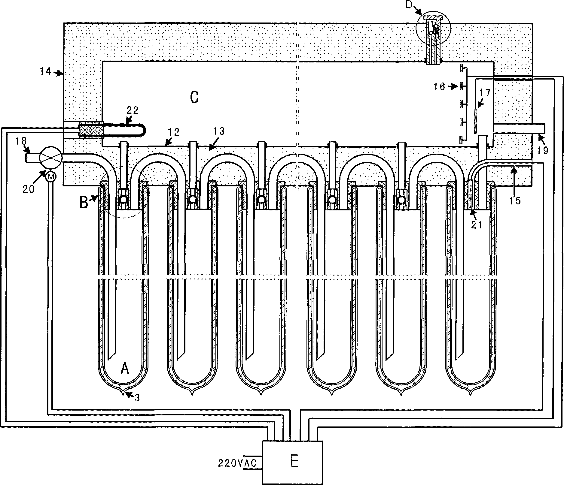
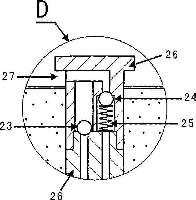
[0020] The present invention will be described in detail below in conjunction with accompanying drawing: figure 1 As shown, the present invention is mainly made up of solar heat collecting tube A, connection seat B, water storage tank C, breathable valve D and controller E.

[0021] The heat collecting tube A is made by sealing both ends of the inner glass tube 1 and the outer glass tube 2 and drawing vacuum from 3 places, and a heat absorbing film layer 4 is compounded on the outer wall of the inner glass tube. Described solar heat collecting tube is the mature product generally in the market now.

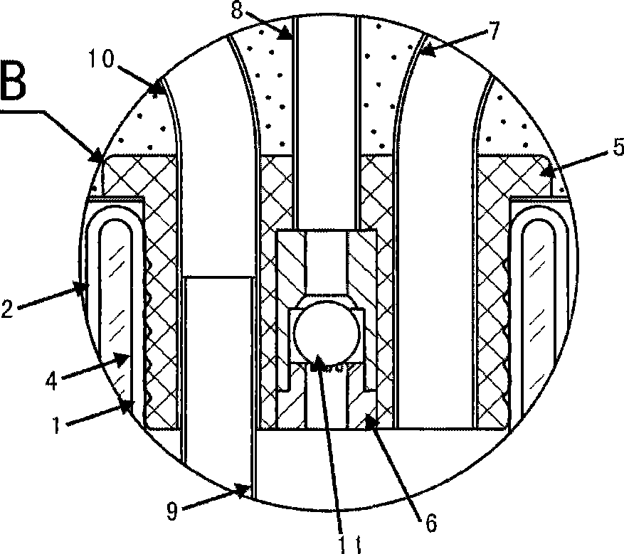
[0022] combined with figure 2 As shown, the connecting seat B includes a sealant 5 , a one-way valve 6 , a U-shaped pipe 7 , a ventilation pipe 8 , a straight-through pipe 9 , and a water inlet pipe 10 . Wherein the one-way valve 7 is a through hole in the middle, and a spherical or conical body 11 with a gap around it is housed therein. The straight-through pipe 9 is inserted...


PUM


Abstract

The invention relates to a photoelectrical complementary solar water heater which mainly comprises solar energy thermal-collecting tubes, a water storage box and a controller. The box body of the water storage box is provided with at least two connecting seats, each connecting seat is internally provided with a check valve, the connecting seats are connected with the solar energy thermal-collecting tubes, a through tube and a U-shaped tube, and the through tube and the U-shaped tube enables the solar energy thermal-collecting tubes to be connected in series and communicated; each solar energy thermal-collecting tube comprises an inside glass tube and an outside glass tube, the inside glass tube and the outside glass tube are sealed at one port to form vacuum between the inside glass tube and the outside glass tube, and a heat absorption film layer is compounded on the outside wall of the inside glass tube; the connecting seats and the water storage box are manufactured to form a whole body; the water storage box mainly comprises a connecting seat, a liner, a shell and insulation materials arranged between the liner and the shell; the box body of the water storage box is provided with a ventilation valve, a water inlet and a water outlet, and the water inlet is connected in series with a water inlet electromagnetic valve. The invention has the advantages of high heat utilization rate, basically consistent used water temperature, no sundry accumulation, difficult scaling, favorable hot water insulation, thermal-collecting tube frost crack prevention, sensitive control, reasonable structure, wide application range, and the like, and is a new safe and reliable environmental-friendly product.

Description

technical field [0001] The invention relates to a solar water heater, in particular to a solar water heater which utilizes sunlight or electric heating for complementary type, and belongs to the technical field of solar energy utilization. technical background [0002] Existing solar water heaters are composed of multiple parallel solar collector tubes and a water storage tank. The water storage tank is located at the upper end, and the upper ends of multiple parallel thermal collector tubes are inserted into the lower part of the water storage tank. It works on the principle that cold water sinks and hot water rises. When in use, the cold water is filled in the water storage tank and poured into the heat collecting pipe, and the water in the heat collecting pipe is gradually warmed up by solar radiation for people to use. Since the heat energy of solar radiation heats up the whole tank of water through the slow heating of the heat collecting tube, and there is a vent hole ...

Claims


Application Information

Patent Timeline
Patent Type & Authority Applications(China)
IPC IPC(8): F24J2/00F24J2/05F24J2/48F24J2/46F24J2/40F24S10/40
CPCY02E10/44
Inventor 周锡明
Owner 周锡明
Learn More