Real-time dynamic monitoring and recording equipment of power system

A real-time dynamic, recording device technology, applied in measurement devices, circuit devices, system integration technology, etc., can solve the problems of poor real situation of line faults, low recording frequency, lack of information exchange and sharing, etc., to achieve flexible and reliable networking and data remote transmission, strengthening dynamic, safe and stable monitoring, and convenient and flexible engineering application.

Active Publication Date: 2009-08-05
SHENZHEN SHUANGHE ELECTRIC CO LTD
View PDF0 Cites 63 Cited by
  • Summary
  • Abstract
  • Description
  • Claims
  • Application Information

AI Technical Summary

Problems solved by technology

[0002] In 2007, China officially adopted IEC 61850 as the power industry standard, and started to change the status quo of repeated data collection of secondary equipment, lack of data integration and processing, and lack of information exchange and sharing
The existing wave recorder in the substation can provide timely and accurate guarantee for user decision-making in the data integration and information exchange between IED equipment, but it only sends data to the main station in the event of a fault, and cannot monitor the operating status of the power system; Synchronized phasor measurement (PhasorMeasurement Unit, referred to as PMU) can monitor the system running status in real time, but the recorded data are only steady-state quantities, and the recording frequency is low, reflecting the real situation of line faults is not good
At present, there is no device that integrates fault recording and PMU with the same hardware platform according to the IEC61850 standard to realize real-time monitoring and recording of the dynamic process of the interconnected grid

Method used


Image

  • Real-time dynamic monitoring and recording equipment of power system
  • Real-time dynamic monitoring and recording equipment of power system
  • Real-time dynamic monitoring and recording equipment of power system

Examples


Embodiment Construction

[0049] The present invention will be further described below with reference to the accompanying drawings and in conjunction with specific embodiments.

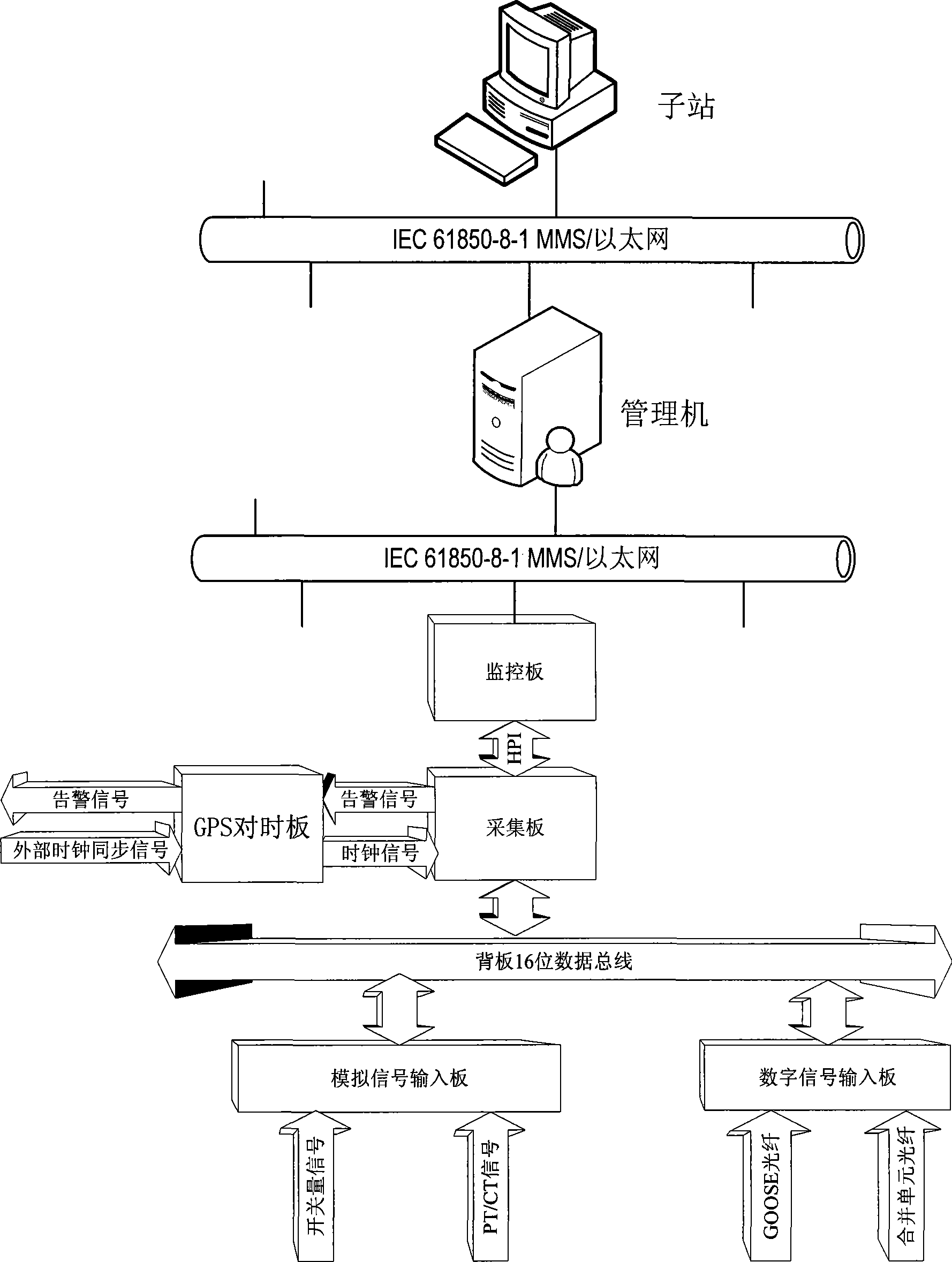
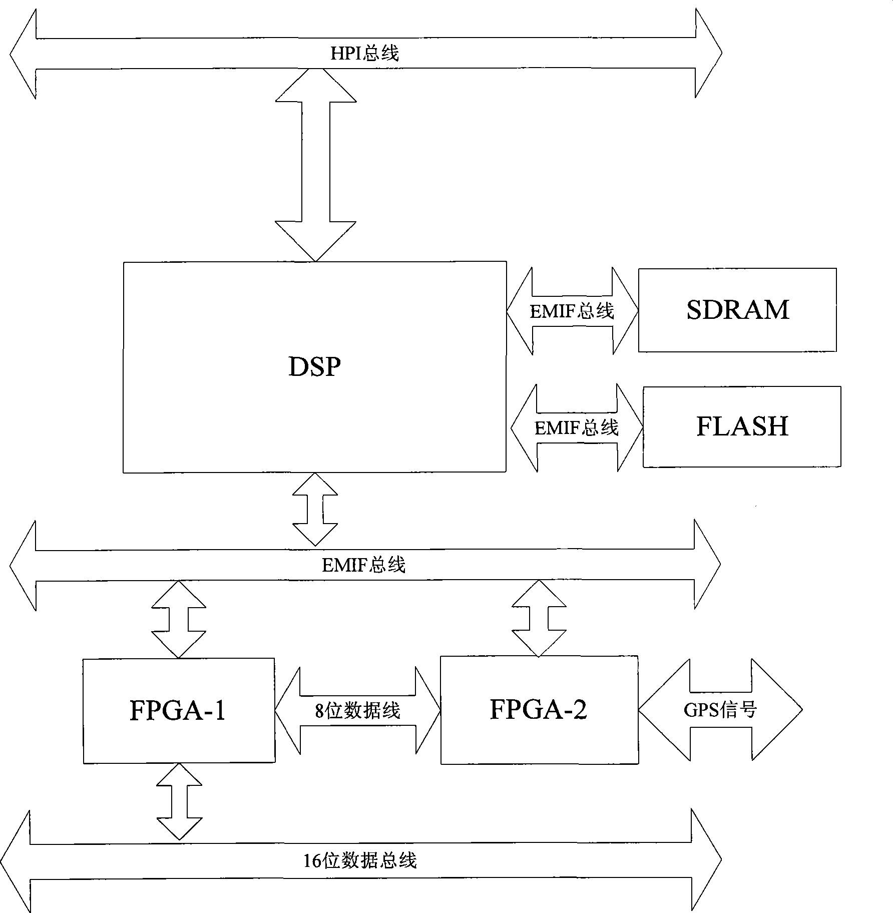
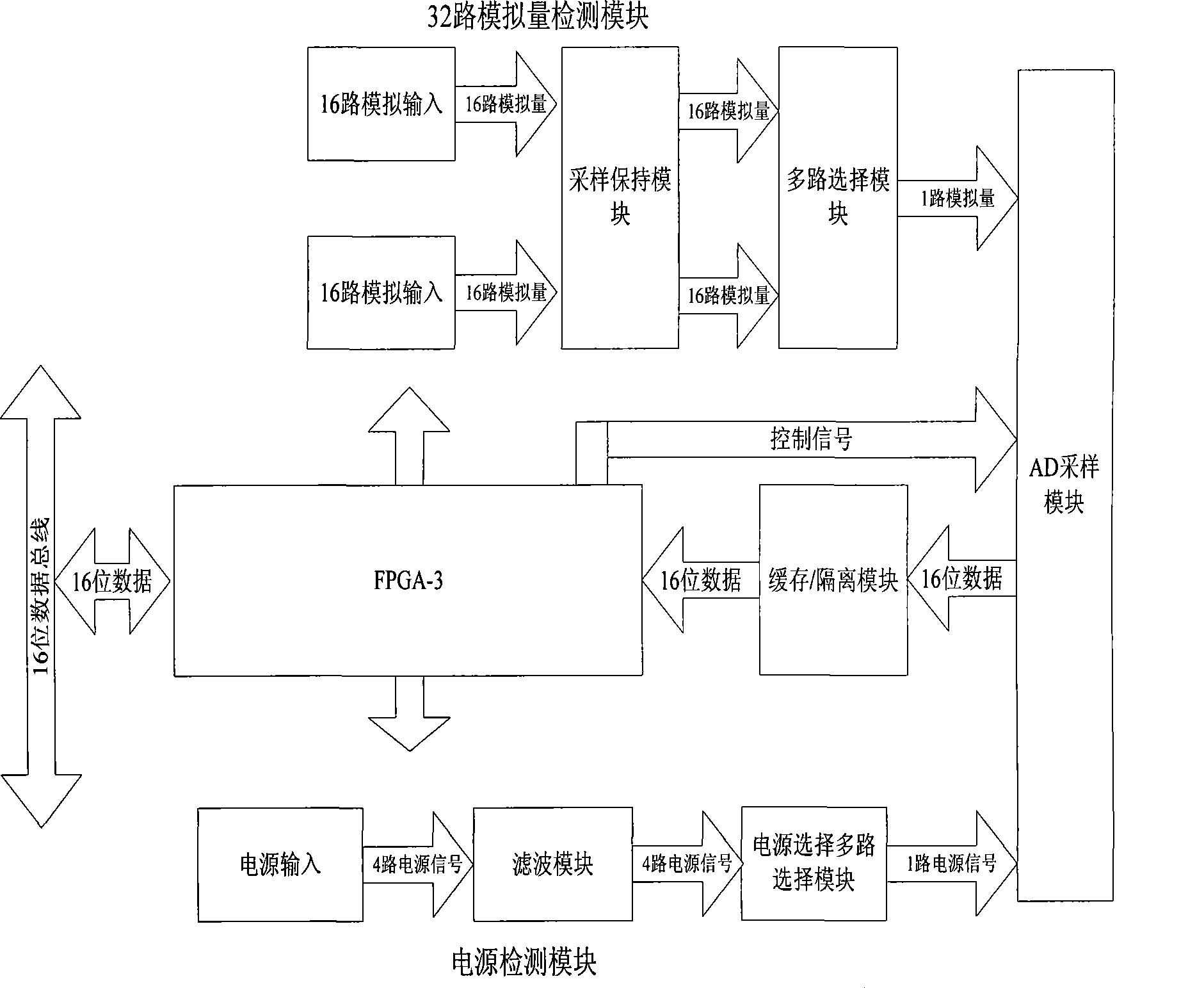
[0050] figure 1 It is a system structure diagram of a specific embodiment of the present invention, in which two signal input methods are given: merging unit + GOOSE network, or traditional PT / CT transmission signal + switch hard node.

[0051] In this specific embodiment, the IEC 61850 model is uniformly established on the server side in accordance with the requirements of the IEC 61850 standard, and a fault recording logic module and a PMU logic module with the same hardware platform are provided. The fault recording logic module performs startup judgment according to the calculation results. Then generate fault files, record transient faults and dynamic data, and complete offline analysis of wave recording data; PMU logic module realizes system voltage, current phasor phase angle and frequency, power online measurement and sy...


PUM


Abstract

The invention relates to a real-time and dynamic monitoring and recording device in the electric power system. IEC61850 models are uniformly established at a server end according to the IEC61850 standard requirement, and a failure wave recording logic module and a PMU logic module which have the same hardware platform are arranged at the server end; the system collocation is realized according to IEC 61850-6; and a separately used collocating tool is formed. The invention respectively models failure wave recording and synchronous phasor measurement into different logic equipment, not only realizes the data record under the condition of failure of the power system, but also realizes synchronous phasor measurement for important substations and power plants of the power system and further builds a real-time and dynamic monitoring system of the power system so as to enhance the monitoring for the dynamic safe stability of the power system and improve the ability of a dispatching mechanism to accurately grasp the running state of the system. The invention can be widely applied to various occasions of wave recording of lines, main substations and machine set as well as synchronous phasor measurement of important power plants and substations.

Description

technical field [0001] The invention relates to monitoring and recording, in particular to a real-time dynamic monitoring and recording device of an electric power system. Background technique [0002] In 2007, China formally adopted IEC 61850 as the power industry standard, and began to change the current situation of repeated data collection of secondary equipment, lack of data integration and processing, and lack of information exchange and sharing. The existing wave recorder in the substation can provide timely and accurate guarantee for user decision-making in the data integration and information exchange between IED equipment, but it only sends data to the master station in the event of a fault, and cannot monitor the operating status of the power system; Synchronized phasor measurement (PhasorMeasurement Unit, referred to as PMU) can monitor the operating status of the system in real time, but the recorded data are only steady-state quantities, and the recording frequ...

Claims


Application Information

Patent Timeline
Patent Type & Authority Applications(China)
IPC IPC(8): G01R31/00G01R31/08H02J13/00
CPCY02E60/728Y04S10/265Y02E40/70Y02E60/00Y04S10/00Y04S10/22
Inventor 耿池勇王一凡溪小宁周磊孔祥兵廖民康
Owner SHENZHEN SHUANGHE ELECTRIC CO LTD
Why Eureka
Try Eureka