Magnetic modulating method and apparatus of hollow filter reactor
A filter reactor and magnetic adjustment technology, applied in harmonic reduction devices, inductors, variable inductors, etc., can solve the problems of small adjustment range of inductance value, complex reactor structure, difficult electrical connection, etc. Simple and compact, reduced material consumption, and the effect of shortening the magnetic circuit
- Summary
- Abstract
- Description
- Claims
- Application Information
AI Technical Summary
Problems solved by technology
Method used
Image
Examples
Embodiment 1
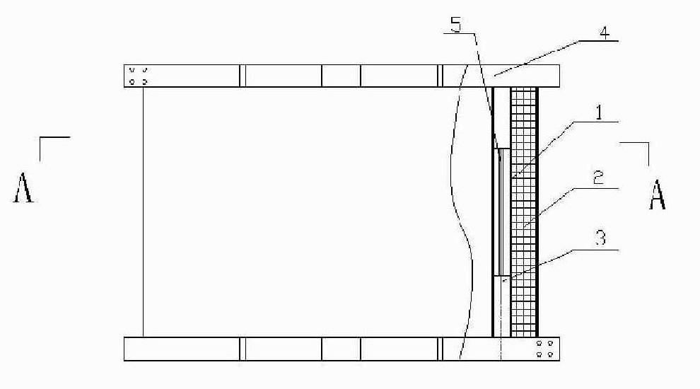
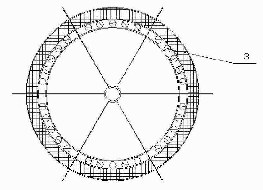
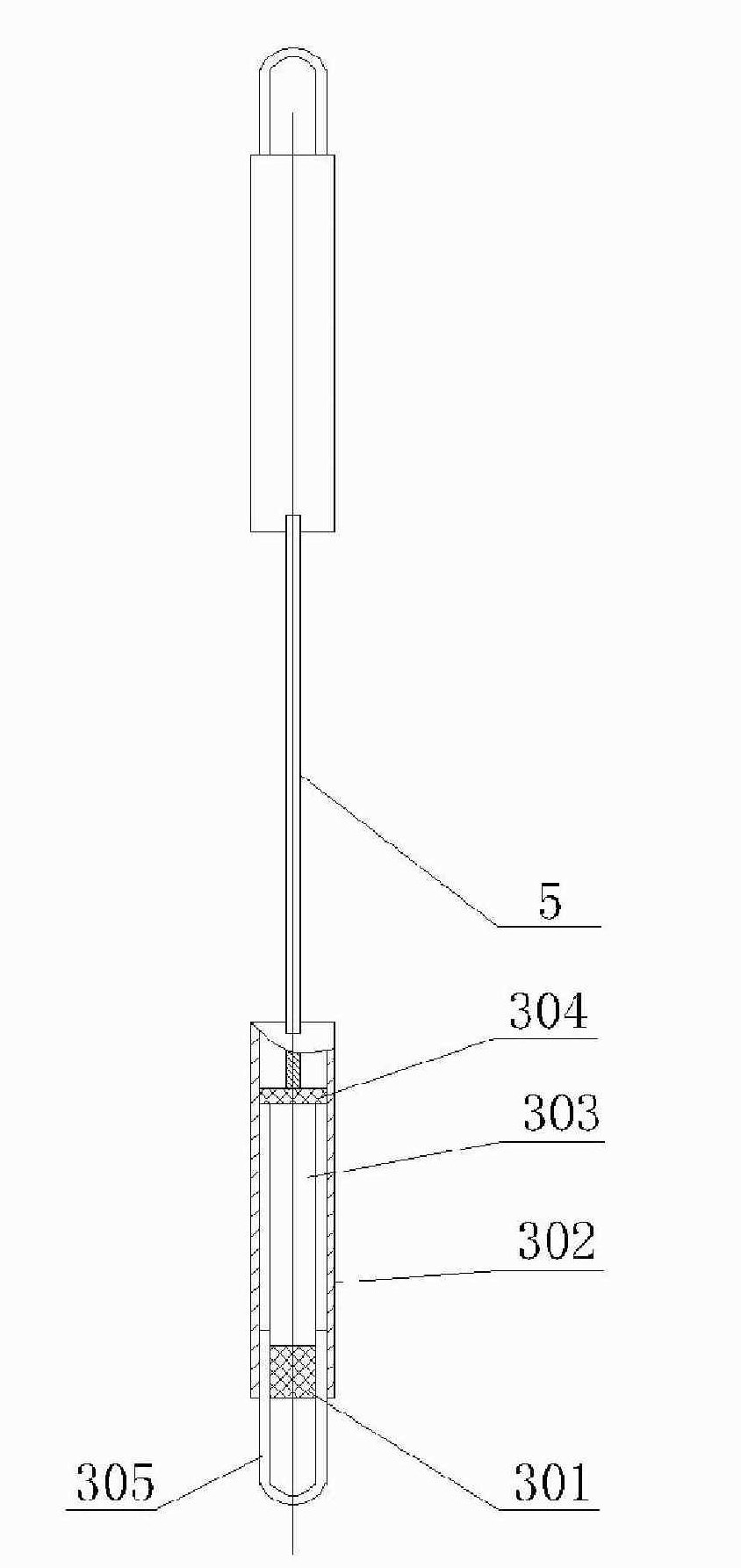
[0020] As shown in the figure, the magnetic field adjustment unit 3 is placed along the direction of the magnetic field line at the upper and lower parts of the coil bobbin 1 located at the inner side of the air-core filter reactor coil 2 where the corresponding magnetic force lines are dense. The magnetic field modulation unit 3 is composed of an insulating sleeve 302, The magnetic rod 303 in the insulating sleeve 302 , the anti-vibration pad 304 , the traction ring 305 bonded on the magnetic rod 303 and the gland 301 inserted in the port of the insulating sleeve 303 are composed. The reluctance is changed by increasing or decreasing the number of magnetic modulation units 3. When all the magnetic modulation units 3 are placed, the inductance value can reach the set maximum adjustment value, that is, increase +5% to +10% on the basis of the original inductance value. %, when all the magnetic modulation units 3 are removed, the inductance value can be adjusted to the minimum, t...
Embodiment 2
[0022] As shown in the figure, the air-core filter reactor magnetic adjustment device has a bobbin 1, on which the main coil 2 is wound, on the top of the bobbin 1 there is a star bus 4, on which the main coil 2 is wound, and on the bobbin 1 The upper and lower parts are located inside the main coil 2 and are provided with a magnetic modulation unit 3 along the direction of the magnetic force line. The magnetic modulation unit 3 is evenly distributed along the circumferential direction. The magnetic modulation unit 3 is made of an insulating sleeve 302 and placed in the insulating sleeve 302 The magnetic rod 303, the anti-vibration rubber pad 304 bonded on the end surface of the magnetic rod 303, the traction ring 305 arranged on the magnetic rod 303 and the gland 301 placed in the port of the insulating sleeve 302 are composed. The traction ring 305 can be bonded on both sides of the magnetic bar 304 . A lead strip 5 is provided between the upper and lower insulating sleeves ...
PUM
 Abstract
Description
Claims
Application Information
 - R&D
- Intellectual Property
- Life Sciences
- Materials
- Tech Scout
- Unparalleled Data Quality
- Higher Quality Content
- 60% Fewer Hallucinations
Browse by: Latest US Patents, China's latest patents, Technical Efficacy Thesaurus, Application Domain, Technology Topic, Popular Technical Reports.
© 2025 PatSnap. All rights reserved.Legal|Privacy policy|Modern Slavery Act Transparency Statement|Sitemap|About US| Contact US: help@patsnap.com


