Mixed switch power source converter and automatic switching control circuit

A switching power supply and hybrid technology, applied in the direction of output power conversion devices, electrical components, etc., can solve the problems of wrong change of working mode, instantaneous jump of current consumption, noise interference, etc., to prevent noise interference and strong anti-interference ability. , to achieve a simple effect

Inactive Publication Date: 2009-08-05
ALLWINNER TECH CO LTD
View PDF1 Cites 66 Cited by
  • Summary
  • Abstract
  • Description
  • Claims
  • Application Information

AI Technical Summary

Problems solved by technology

The converter described in this paper realizes the automatic switching mode by detecting the magnitude of the load current, but due to the large-scale digital circuit as the load, its current consumption will inevitably have freq

Method used


Image

  • Mixed switch power source converter and automatic switching control circuit
  • Mixed switch power source converter and automatic switching control circuit
  • Mixed switch power source converter and automatic switching control circuit

Examples


Example Embodiment

[0024] Hereinafter, the present invention will be explained by taking a DC-DC converter with PWM and PFM working modes as an example.
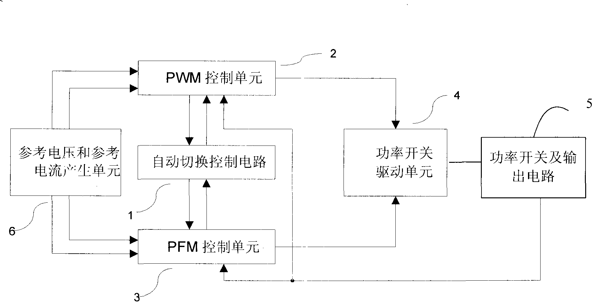
[0025] figure 1 Shown is a block diagram of a DC-DC converter circuit. figure 1 In the converter, the automatic switching control circuit 1 is used to connect the PWM control unit 2, the PFM control unit 3, and the power switch drive unit 4. The reference voltage and reference current generating unit 6 is connected to the PWM control unit 2 and the PFM control unit 3; the PWM control unit 2 and the PFM control unit 3 are also connected to the power switch drive unit 4, the power switch and the output circuit 5, respectively. The power switch driving unit 4 is connected to the power switch and the output circuit 5 to adjust the output voltage of the converter.

[0026] The reference voltage and reference current generating unit 6 generates at least one reference voltage signal and at least one reference current signal; when the PWM control unit ...


PUM


Abstract

The invention provides a mixed switch power converter, comprising a reference voltage and reference current generation unit, a PWM/PFM control unit, a power switch driving unit, a power switch and output circuit, and an auto-switch control circuit. The reference voltage and reference current generation unit is used for generating a reference voltage signal and a reference current signal; the PWM/PFM control unit is used for obtaining a voltage feedback signal and a current feedback signal, receiving the reference voltage signal and the reference current signal, outputting a first detection signal and a voltage detection signal and outputting a PWM/PFM control logic signal according to a received working model selection signal; the power switch driving unit is used for receiving the control logic signal and outputting a driving signal; the power switch and output circuit is turned on and turned off according to the driving signal; and the auto-switch control circuit is used for receiving the first detection signal and the voltage detection signal, counting the first detection signal and the voltage detection signal in a predetermined time and outputting the mode selection signal when the counting result reaches a predetermined threshold value. The invention also provides the auto-switch control circuit. The invention can improve the transfer efficiency and the anti-interference performance of the converter within the whole load range.

Description

technical field [0001] The invention relates to a hybrid switching power converter with two working modes of PWM and PFM and an automatic switching control circuit for realizing automatic switching of the hybrid switching power converter. Background technique [0002] Due to the increasing popularity of portable consumer electronic products, the switching power supply technology of portable electronic devices has been rapidly developed. A switching power supply usually has two working modes, PWM (Pulse Width Modulation, pulse width modulation) and PFM (Pulse Frequency Modulation, pulse frequency modulation), and the two working modes are converted by a hybrid switching power supply converter. Hybrid switching power converters are widely used in portable electronic devices. [0003] In the PWM working mode, the hybrid switching power converter works at a constant switching frequency, and the PWM control unit adjusts the conduction time of the power switch according to the lo...

Claims


Application Information

Patent Timeline
IPC IPC(8): H02M1/00H02M1/06H02M1/08
Inventor 邢涛
Owner ALLWINNER TECH CO LTD
Why Eureka
Try Eureka