
Refrigeration system

A refrigeration device and refrigerant technology, which is applied in the direction of exhaust devices, mufflers, refrigerators, etc., and can solve the problems of increased pressure pulsation, increased refrigerant density and sound velocity, etc.

Active Publication Date: 2009-08-05
DAIKIN IND LTD
View PDF2 Cites 8 Cited by
  • Summary
  • Abstract
  • Description
  • Claims
  • Application Information

AI Technical Summary

Problems solved by technology

However, when carbon dioxide is used as the refrigerant of the refrigeration unit in this way, the density and sound velocity of the refrigerant will increase, which will inevitably cause the problem of increased pressure pulsation.

Method used


Image

  • Refrigeration system
  • Refrigeration system
  • Refrigeration system

Examples


Embodiment Construction

[0092]

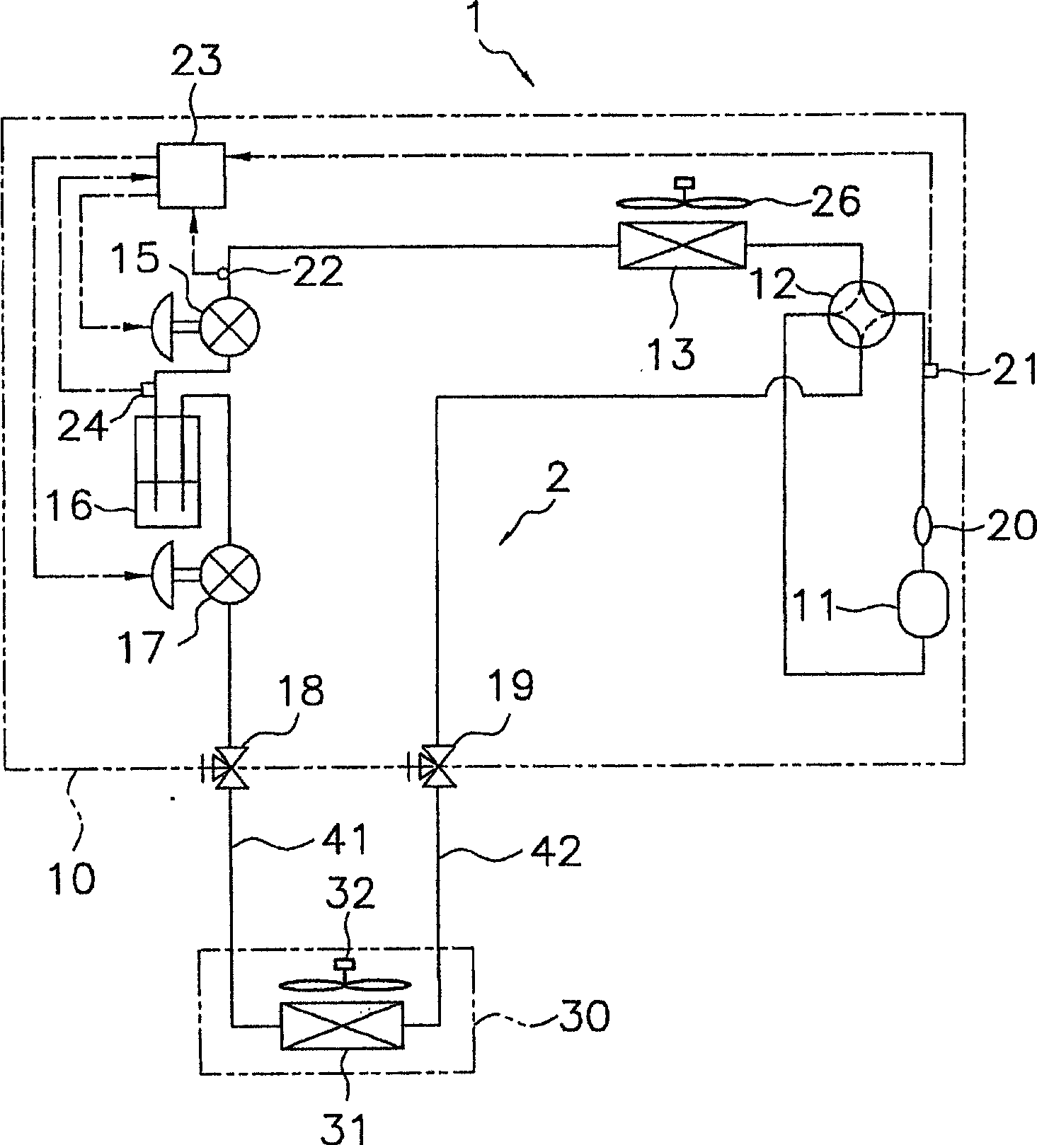
[0093] figure 1 A schematic refrigerant circuit 2 of the air-conditioning apparatus 1 according to the embodiment of the present invention is shown in .

[0094] This air conditioner 1 is an air conditioner that uses carbon dioxide as a refrigerant and can perform cooling operation and heating operation, and is mainly composed of a refrigerant circuit 2, blowing fans 26, 32, a control device 23, a high pressure sensor 21, a temperature sensor 22 and The intermediate pressure sensor 24 and the like are configured.

[0095] The refrigerant circuit 2 is mainly equipped with a compressor 11, a π-type muffler 20, a four-way switching valve 12, an outdoor heat exchanger 13, a first electric expansion valve 15, an accumulator 16, a second electric expansion valve 17 and Indoor heat exchanger 31, such as figure 1 As shown, the units are connected via refrigerant conduits.

[0096] Furthermore, in the present embodiment, the air conditioner 1 is a separate air conditioner...


PUM


Abstract

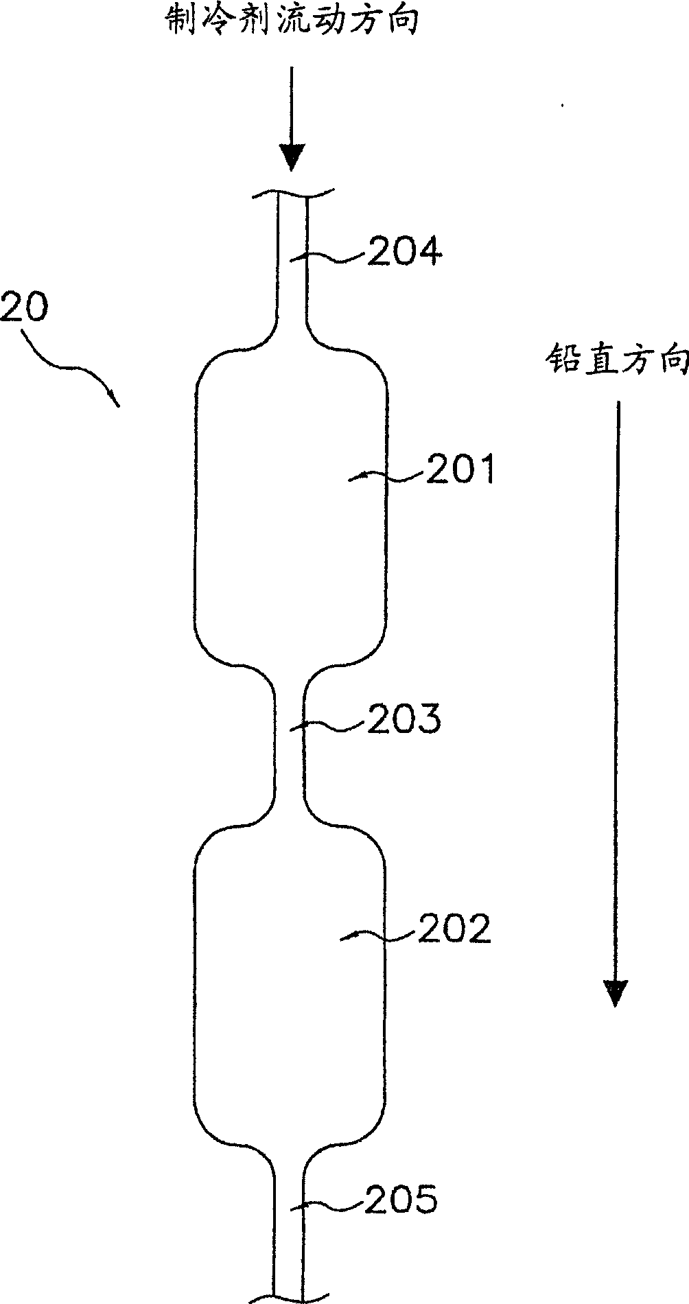
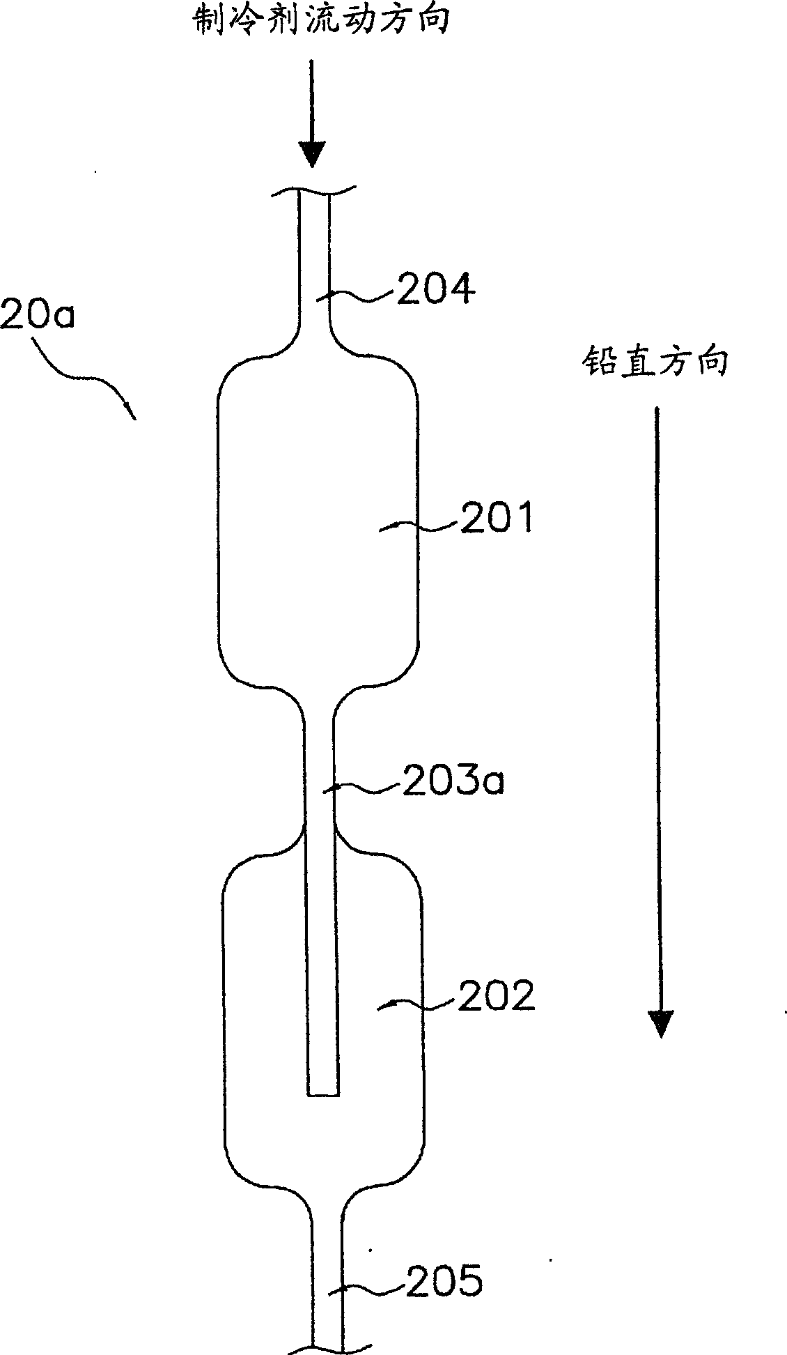
A refrigeration system employing carbon dioxide, or the like, as refrigerant of which the pulsation of pressure is reduced sufficiently. The refrigeration system (1) comprises a first refrigerant path (204), p type mufflers (20, 20a), and a second refrigerant path (205). The p type muffler has a first silence space (201), a second silence space (202), and communication paths (203, 203a). The first silence space communicates with the first refrigerant path. The second silence space is arranged below the first silence space. The communication path extends from the lower end of the first silence space toward the outside of the first silence space, and communicates with the second silence space. The second refrigerant path extends from the lower end of the second silence space.

Description

technical field [0001] The invention relates to a refrigeration device, in particular to a refrigeration device using a π-type silencer as the silencer. Background technique [0002] In recent years, refrigerators using carbon dioxide as a refrigerant have been commercialized. However, when carbon dioxide is used as the refrigerant of the refrigerating apparatus in this way, the density and sound velocity of the refrigerant increase, which inevitably causes a problem of increased pressure pulsation. In response to such a problem, in recent years, various methods of reducing the pressure pulsation of the refrigeration system have been proposed (for example, refer to Patent Document 1, Patent Document 2, Non-Patent Document 1, and Non-Patent Document 2). [0003] Patent Document 1: Japanese Patent Application Laid-Open No. 6-10875 [0004] Patent Document 2: Japanese Patent Laid-Open No. 2004-218934 [0005] Unlicensed Document 1: Yamada , Otani , "オリフイスおよびπ-type arrang...

Claims


Application Information

Patent Timeline
Patent Type & Authority Applications(China)
IPC IPC(8): F25B41/00F01N7/02F16L55/02F01N13/02
CPCF25B13/00F25B31/02F25B9/008F25B2500/12F04B39/0061F25B2313/02741F25B41/00
Inventor 石川谕增田正典樋口顺英
Owner DAIKIN IND LTD
Learn More