Permanent magnet type rotary electric device rotor
A permanent magnet and rotating motor technology, applied to synchronous motors with stationary armatures and rotating magnets, magnetic circuit rotating parts, magnetic circuit shape/style/structure, etc., can solve the deterioration of comprehensive operating efficiency, motor loss, etc. problem, achieve the effect of improving manufacturability, improving efficiency, and reducing rare materials
- Summary
- Abstract
- Description
- Claims
- Application Information
AI Technical Summary
Problems solved by technology
Method used
Image
Examples
no. 1 approach
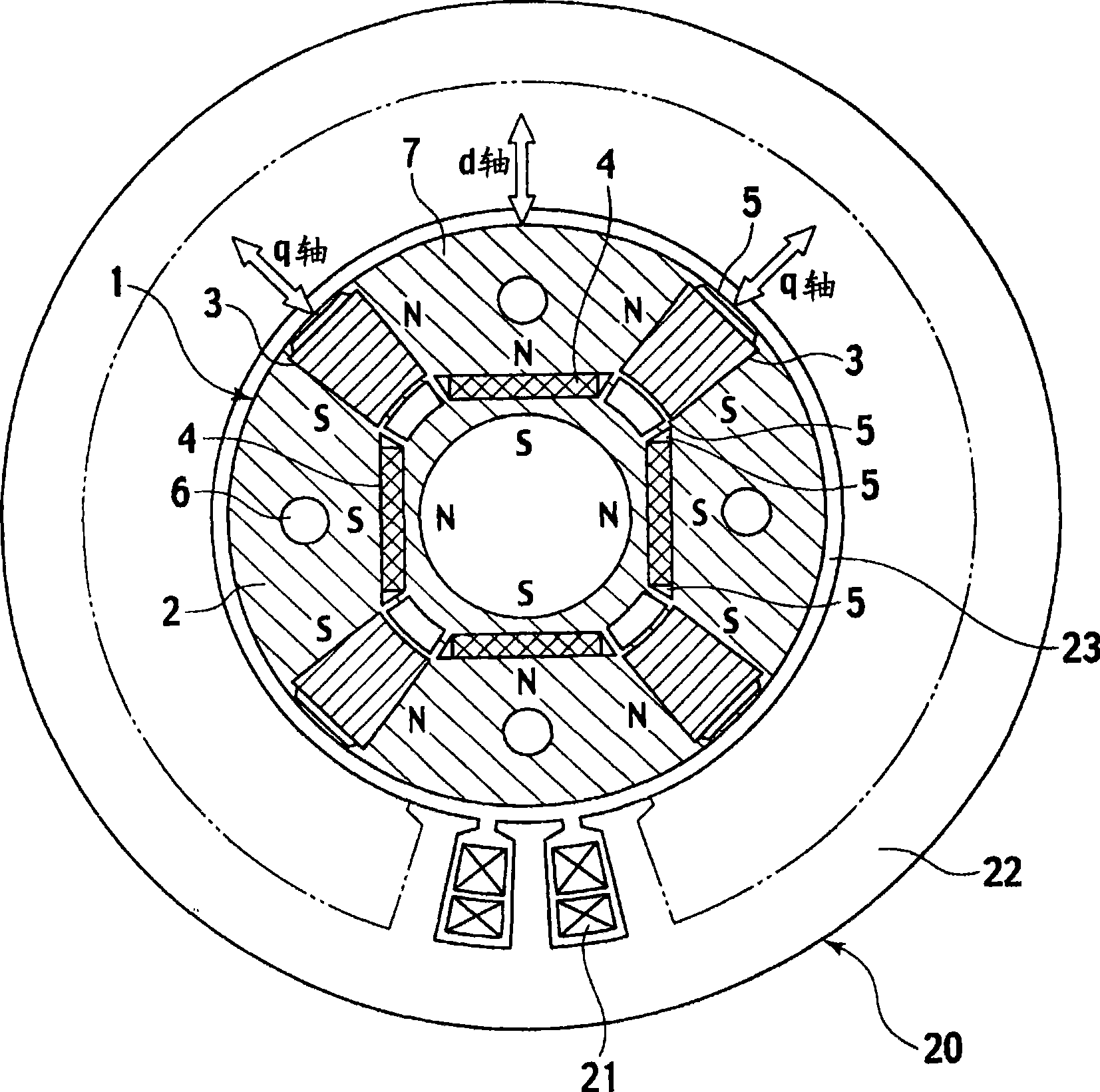
[0031] use Figure 1 to Figure 5 , the permanent magnet type rotating electrical machine according to the first embodiment of the present invention will be described. figure 1 The structure of the permanent magnet type rotating electrical machine according to the present embodiment is shown, and the rotor 1 is accommodated inside the stator 20 so as to face each other across the air gap 23 . In addition, the stator 20 can employ|adopt the stator of the general structure which can be used as an AC motor. In this embodiment, the Figure 9 The stator 20 of the conventional example shown is the same stator.
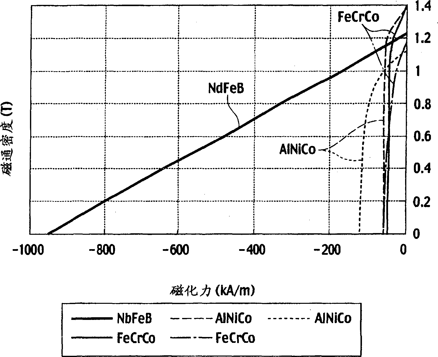
[0032]The rotor 1 of the present embodiment includes a rotor core 2 , first permanent magnets 3 having a small product of coercive force and thickness in the magnetization direction, and second permanent magnets 4 having a large product of coercive force and thickness in the magnetization direction. The rotor core 2 is formed by laminating silicon steel sheets, and the fir...
no. 2 approach
[0063] A permanent magnet type rotating electrical machine according to a second embodiment of the present invention is figure 1 The permanent magnet type rotating electrical machine of the first embodiment shown is characterized in that an NdFeB magnet with a small amount of Dy element is used as the second permanent magnet 4 having a large product of coercive force and thickness in the magnetization direction. Therefore, other configurations with figure 1 It is common to the first embodiment shown.
[0064] When the Dy element is small, the residual magnetic flux density of the permanent magnet is high, and at 20° C., a residual magnetic flux density of 1.33 T or higher can be obtained.
[0065] When the conventional rotating electric machine reaches a high speed, in order to suppress a voltage rise due to an induced voltage, flux weakening control is performed by a negative d-axis current. At this time, an excessively large reverse magnetic field acts on the permanent m...
no. 3 approach
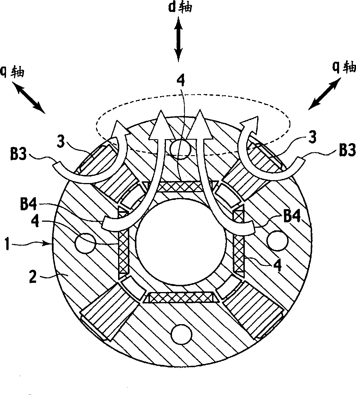
[0070] use Figure 6 The configuration diagram of the rotor 1 in FIG. 10 illustrates a permanent magnet type rotating electric machine according to a third embodiment of the present invention. The permanent magnet type rotating electrical machine of the present embodiment consists of Figure 6 The illustrated rotor 1 is constituted by a stator 20 accommodating it. Then, the stator 20 is the same as the other embodiments, figure 1 ,Figure 9 composition shown. In addition, in Figure 6 in, right with figure 1 Components common to the first embodiment shown are denoted by the same reference numerals.
[0071] Such as Figure 6 As shown, in the rotor 1 of this embodiment, the second permanent magnet 4 of an inverted U-shaped NdFeB magnet is embedded in the rotor core 2 so as to protrude toward the outer peripheral side. The central axis of the inverted U-shape of the second permanent magnet 4 is at a position coincident with the d-axis. The first permanent magnet 3 of th...
PUM
 Abstract
Description
Claims
Application Information
 - R&D
- Intellectual Property
- Life Sciences
- Materials
- Tech Scout
- Unparalleled Data Quality
- Higher Quality Content
- 60% Fewer Hallucinations
Browse by: Latest US Patents, China's latest patents, Technical Efficacy Thesaurus, Application Domain, Technology Topic, Popular Technical Reports.
© 2025 PatSnap. All rights reserved.Legal|Privacy policy|Modern Slavery Act Transparency Statement|Sitemap|About US| Contact US: help@patsnap.com


