Micro water grinding head for edge grinding machine

An edger and water mill technology, which is applied to the parts of grinding machine tools, machine tools suitable for grinding the edge of workpieces, grinding machines, etc., can solve the problems of low edge grinding efficiency, large heat generation of grinding wheels, and large consumption of grinding wheels, etc. Achieve the effect of high edging efficiency, good edging quality and slow grinding wheel wear

Inactive Publication Date: 2009-08-12
佛山市一鼎科技有限公司
View PDF0 Cites 1 Cited by
  • Summary
  • Abstract
  • Description
  • Claims
  • Application Information

AI Technical Summary

Problems solved by technology

The traditional edging machine uses a water spray device to spray a large amount of water on the grinding wheel to cool the grinding wheel and eliminate dust. The grinding efficiency is high and the edging quality is high. However, a large amount of sewage is generated during the production process and a large amount of water resources are wasted.
At the same time, sewage treatment is difficult, which is not conducive to environmental protection
In addition, the tiles after edge grinding need to be dried

Method used


Image

  • Micro water grinding head for edge grinding machine
  • Micro water grinding head for edge grinding machine
  • Micro water grinding head for edge grinding machine

Examples


Embodiment 1

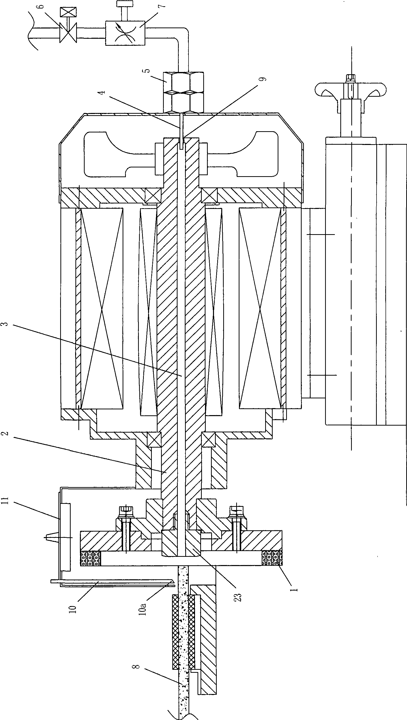
[0010] see figure 1 The micro-water edging head of the edging machine includes a grinding wheel 1 and a rotating shaft 2 that drives the grinding wheel 1 to rotate, and the grinding wheel 1 is fixed on one end of the rotating shaft 2 . As the best implementation mode, the rotating shaft 2 of this embodiment is the motor shaft, which makes the overall structure the simplest and most compact. The rotating shaft 2 is connected with a water supplier 4 . A water delivery channel 3 connected to the water supply is opened in the rotating shaft 2, and the water delivery channel 3 runs through to one end of the fixed grinding wheel of the rotating shaft. The water supply device of this embodiment is a water delivery pipe 4 inserted into the water delivery channel 3, and the water delivery pipe 4 is inserted from the end face of the rotating shaft 2 without a fixed grinding wheel. The water pipe 4 is fixed on the motor housing by a nut 5 . In order to facilitate the control of the wa...

Embodiment 2

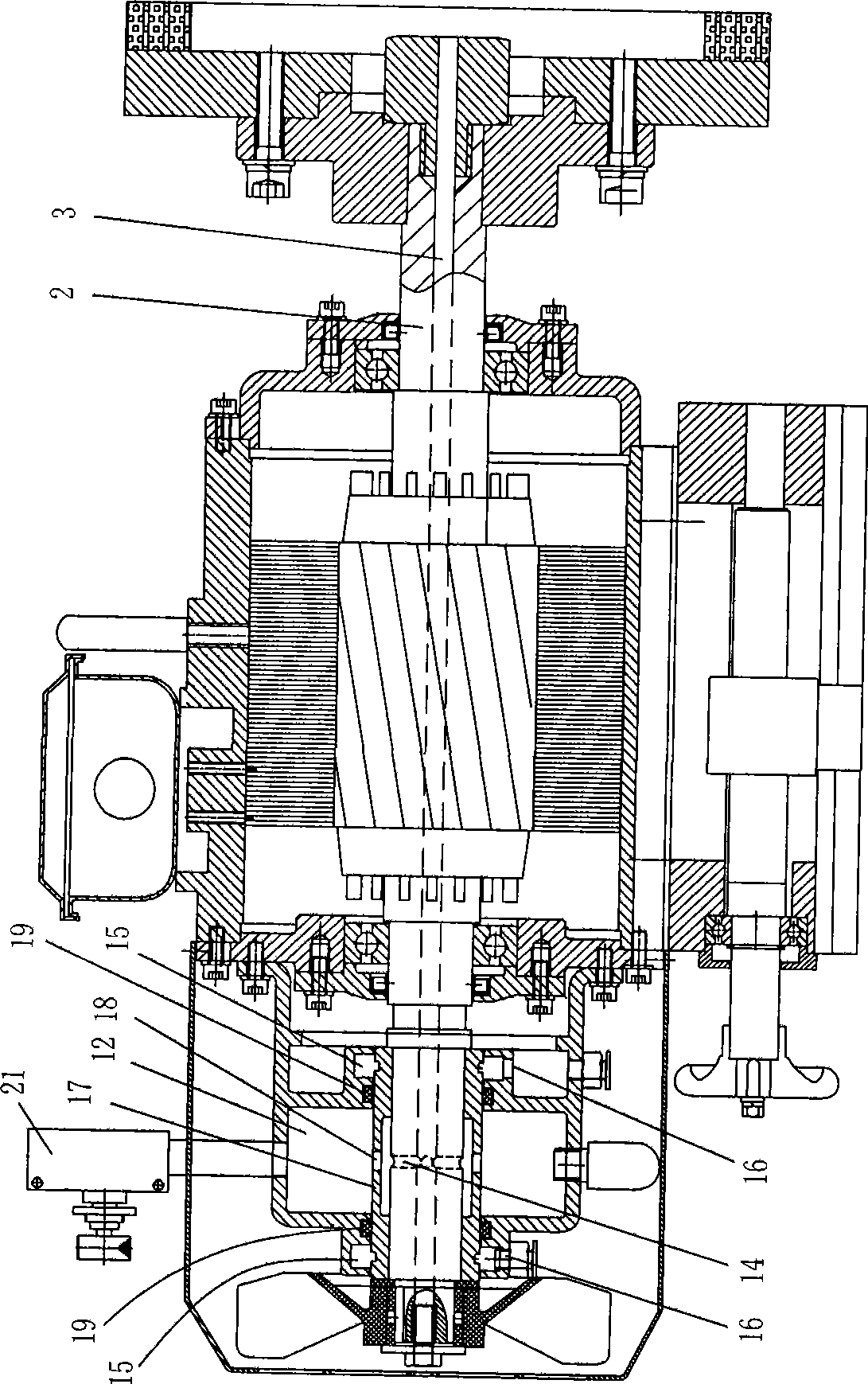
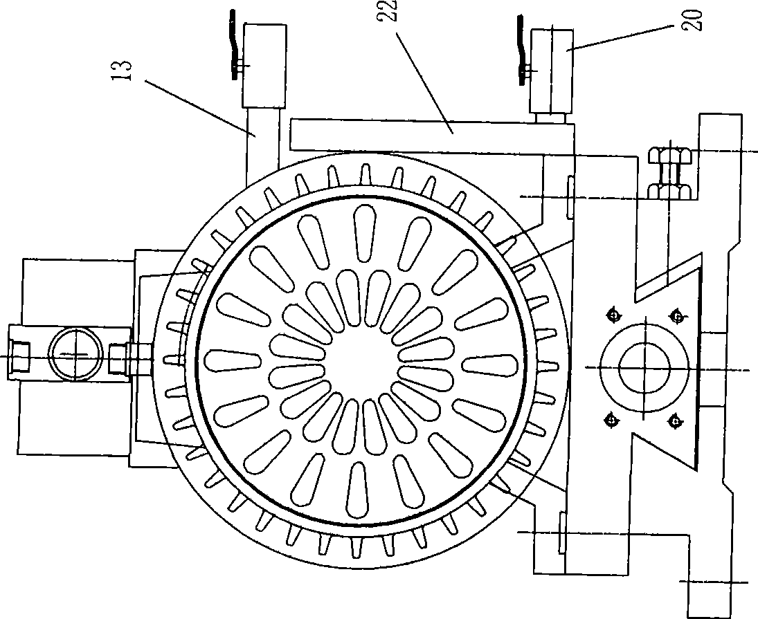
[0012] see figure 2 , image 3 , The difference between this embodiment and Embodiment 1 lies in the structure of the water supply device to which the rotating shaft 2 is connected. The water supplier in this embodiment is a fixed water storage chamber 12 that is rotatably coupled with the rotating shaft 2 , and the water storage chamber is connected with a water inlet pipe 13 . A radial through hole 14 is opened in the rotating shaft, and the through hole 14 communicates the water delivery channel 3 with the water storage chamber 12 . The cooling water delivered by the external water source first enters the water storage chamber 12 from the water inlet pipe 13, then enters the water delivery channel 3 from the water storage chamber 12, and finally flows out from the end surface of the rotating shaft.

[0013] In order to prevent the water in the water storage chamber 12 from leaking out so as to affect the safe operation of other parts (such as motors) in the edging machin...


PUM


Abstract

The invention provides a brackish water edging head of an edge grinding machine which comprises a grinding wheel and a shaft that drives the grinding wheel to rotate. The grinding wheel is fixed on one end of the shaft which is characterized in that the shaft communicates communicate with a water feeder. A water conveyance channel which communicates with the water feeder is arranged in the shaft. The water conveyance channel runs through the end of the shaft for fixing the grinding wheel. When the edge grinding machine runs, an external water source slowly inputs cooling water into the water conveyance channel in the shaft by the water feeder. The cooling water flows out from the end of the shaft which is fixed with the grinding wheel and drops on the grinding wheel that rotates in high speed. Thus, the grinding wheel and work pieces are under the water lubrication and temperature lowering effects. Currents are slow, therefore, the cooling water dropping on the grinding wheel cannot produce flowing sewage. The brackish water edging head of the edge grinding machine overcomes both shortages of large water consumption and hard sewage processing of a traditional wet edge grinding machine and shortages of poor grinding quality, low grinding efficiency and fast grinding wheel loss of a traditional dry edge grinding machine.

Description

technical field [0001] The invention relates to the structure of an edger used in processing industries such as ceramics and stone, especially the structure of a grinding head in the edger. Background technique [0002] The edge grinding machine used in ceramics, stone and other processing industries is mainly used for grinding and shaping the four sides of ceramic tiles and stone. The traditional edging machine uses a water spray device to spray a large amount of water on the grinding wheel to cool the grinding wheel and eliminate dust. The grinding efficiency is high and the edging quality is high. However, a large amount of sewage is generated during the production process and a large amount of water resources are wasted. At the same time, sewage treatment is difficult, which is not conducive to environmental protection. Have again, the ceramic tile after the edging needs to carry out follow-up complicated process and carry out drying treatment before packing, the proces...

Claims


Application Information

Patent Timeline
IPC IPC(8): B24B9/06B24B41/04
Inventor 冯竞浩
Owner 佛山市一鼎科技有限公司
Why Eureka
Try Eureka