Matched mould locking mechanism of hollow plastic forming machine

A technology of locking mechanism and forming machine, which is applied to hollow objects, other household appliances, household appliances, etc., which can solve the problems of difficulty in processing and installation, poor movement stability, and large number of parts, so as to achieve convenient installation and maintenance and save energy. Material, high reliability effect

Active Publication Date: 2010-12-29
SUZHOU TONGDA MACHINERY
View PDF3 Cites 7 Cited by
  • Summary
  • Abstract
  • Description
  • Claims
  • Application Information

AI Technical Summary

Problems solved by technology

[0004] The applicant believes that although the above-mentioned CN2705301Y has the technical effects mentioned in the 13th-14th line on page 3 of its specification, it still has the following deficiencies: first, the number of parts is large and the assembly relationship between the parts is complicated, such as The slider seat cover 2 needs to be fixed with the fixed cover 1 by a set of screws (four screws in the figure), so that the slider seat cover 2 is positioned in the cavity of the fixed cover 1 and located at one end of the cavity, and the The outer wall of one end of the big head of the slider seat cover 2 forms a seal with the inner wall of the cavity. Another example is to accommodate the piston 3 in the other end of the cavity of the fixed sleeve 1, and pass the outer wall of the piston 3 through multiple sealing rings and the inner wall of the cavity. Form a reliable seal between them, and if it is necessary to form a seal between the outer wall of the small end of the slider seat cover 2 and the inner wall of the piston 3, and it is necessary to set up a hydraulic oil inlet and outlet hole 12 on the fixed sleeve 1, etc., so as to give Difficulties in processing and installation; the second is that the movement stability of a group of sliders 6 entering from the slider separation chamber 4 into the slider engagement chamber 5 or from the slider engagement chamber 5 into the slider separation chamber 4 is poor, resulting in separation and engagement All requirements cannot achieve the expected effect, because the energy of the spring cover 8 that pushes the slider 6 comes from the large spring 9, and the large spring 9 cannot avoid the inherent elasticity of the spring, that is, after a period of use, it will collapse due to fatigue. The spring force is changed, and the effect of a group of small springs 10 on the piston 3 has the same defect as that of the large spring 9. When a group of small springs 10 were activated at the beginning, the resistance to the piston 3 was relatively large. The elongation and compression coefficient of the small spring 10 change, so that the oil volume of the mobile hydraulic oil used to push the piston 3 that enters from the oil inlet and outlet holes 12 changes, and it is easy to cause the slide block 6 and the clamping cylinder to be locked. Poor engagement between the cylinder columns directly affects the locking effect of the left and right mold halves. Perhaps the patent has been aware of this, so a piston position detection switch is provided on the fixed sleeve 1 so as to detect when the piston 3 is fixed. The left and right positions in the cavity of set 1 (for details, see lines 6-11 on page 5 of the patent specification)
The applicant conducted a comprehensive search, but did not retrieve any technical information on the mold clamping and locking mechanism with a simpler structure than the above

Method used


Image

  • Matched mould locking mechanism of hollow plastic forming machine
  • Matched mould locking mechanism of hollow plastic forming machine
  • Matched mould locking mechanism of hollow plastic forming machine

Examples


Embodiment

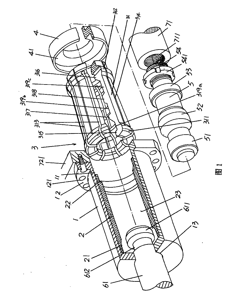
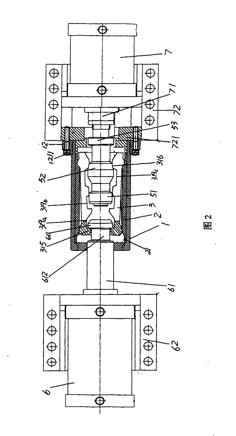
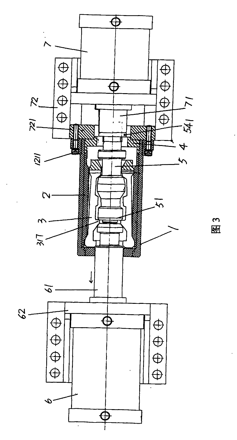
[0023] Please refer to Fig. 1, the fixed cover 1 of a tubular body is shown among the figure, take the position state shown in Fig. 1 as example at present, the central region of the left end of this fixed cover 1 offers a clamping oil cylinder column hole 13, In order to be used for protruding into or withdrawing from the top end of the first cylinder column 61 of the clamping cylinder 6 shown in Fig. 2 to Fig. 4 and having the same structure as the prior art such as the above-mentioned CN2705301Y, the It can be seen that a lock pin 611 is formed at the top end of the first cylinder column 61, and a neck with a diameter obviously smaller than that of the first cylinder column 61 is formed between the pin pin 611 and the cylinder column body of the first cylinder column 61. 612. When the mold is to be clamped and the mold is locked, then the lock pin 611 of the first cylinder column 61 enters the fixed sleeve 1 , otherwise it exits the fixed sleeve 1 . A mating flange 12 is f...


PUM


Abstract

A die assembly locking mechanism of a hollow plastic molding machine belongs to the technical field of hollow plastic product molding machine and comprises a fixed sleeve, a lock sliding bush, an expansion sleeve, a pressing sleeve and an interlocking bar. The locking sliding bush is fixedly installed inside the fixed sleeve, and a first lock lug boss chamber is formed at one end of the lock sliding bush, and a second lock lug boss chamber is formed at the other end; the expansion sleeve is held inside the expansion sleeve chamber of the lock sliding bush, and the expansion sleeve is formed by a group of lock catches with same structure for enclosing a barrel body together; a first lock lug boss is formed at one end of each lock catch, and a second lock lug boss is formed at the other endof each lock catch; the pressing sleeve is installed inside a pressing sleeve chamber at one end of the fixed sleeve. The interlocking bar is held inside the expansion sleeve and is matched with the lock matches. The invention has the advantages of convenient process, installation and maintenance, and the material can be saved; the reliability of die assembly locking is high; and the expansion sleeve moves stably in the lock sliding bush, and cannot be degenerated as time goes on.

Description

technical field [0001] The invention belongs to the technical field of hollow plastic product molding machines, and in particular relates to a mold clamping and locking mechanism of a hollow plastic molding machine, which is used for locking a left half mold and a right half mold correspondingly installed on a pair of mold frames. Background technique [0002] As is well known in the industry, the hollow plastic molding machine is usually equipped with a mold clamping and locking mechanism, which is also called a mold locking mechanism, and its duty is to place a pair of molds on the hollow plastic molding machine face to face. Lock the half-molds on the formwork, that is, the left half-mold and the right half-mold. [0003] Chinese utility model patent authorization announcement number CN2705301Y discloses a mold clamping and locking mechanism for plastic hollow molding machines. It lacks and overcomes the disadvantages of the double-plate mold clamping mechanism recommend...

Claims


Application Information

Patent Timeline
Patent Type & Authority Patents(China)
IPC IPC(8): B29C49/56B29L22/00
Inventor 邱建成褚元洪徐文良
Owner SUZHOU TONGDA MACHINERY
Why Eureka
Try Eureka