Simulating device for solar cavity type heat absorber

A technology of simulating device and heat absorber, applied in the research field of tower solar thermal power generation, which can solve the problems of low heat flux density, high heat flux density, and inability to provide such a large heat flux density.

Inactive Publication Date: 2009-08-12
XI AN JIAOTONG UNIV
View PDF0 Cites 12 Cited by
  • Summary
  • Abstract
  • Description
  • Claims
  • Application Information

AI Technical Summary

Problems solved by technology

However, the solar heat flux inside the cavity heat absorber has two notable features: one is that the heat flux is very large, generally at 100kW / m 2 Above, the highest place can reach 500kW / m 2 , or even higher, general quartz lamp heating or electric furnace wire heating cannot provide such a large heat flux; second, because the distribution of solar spots in the cavity heat absorber is uneven, the heat flux distribution is uneven, and the heat flux directly facing the cavity The heat flux density on the back wall of the daylight opening of the type heat absorber is relatively the largest, while the heat flux density on several surfaces around the daylight opening is relatively minimum
Therefore, it is more difficult to simulate the cavity heat absorber

Method used


Image

  • Simulating device for solar cavity type heat absorber
  • Simulating device for solar cavity type heat absorber
  • Simulating device for solar cavity type heat absorber

Examples


Embodiment Construction

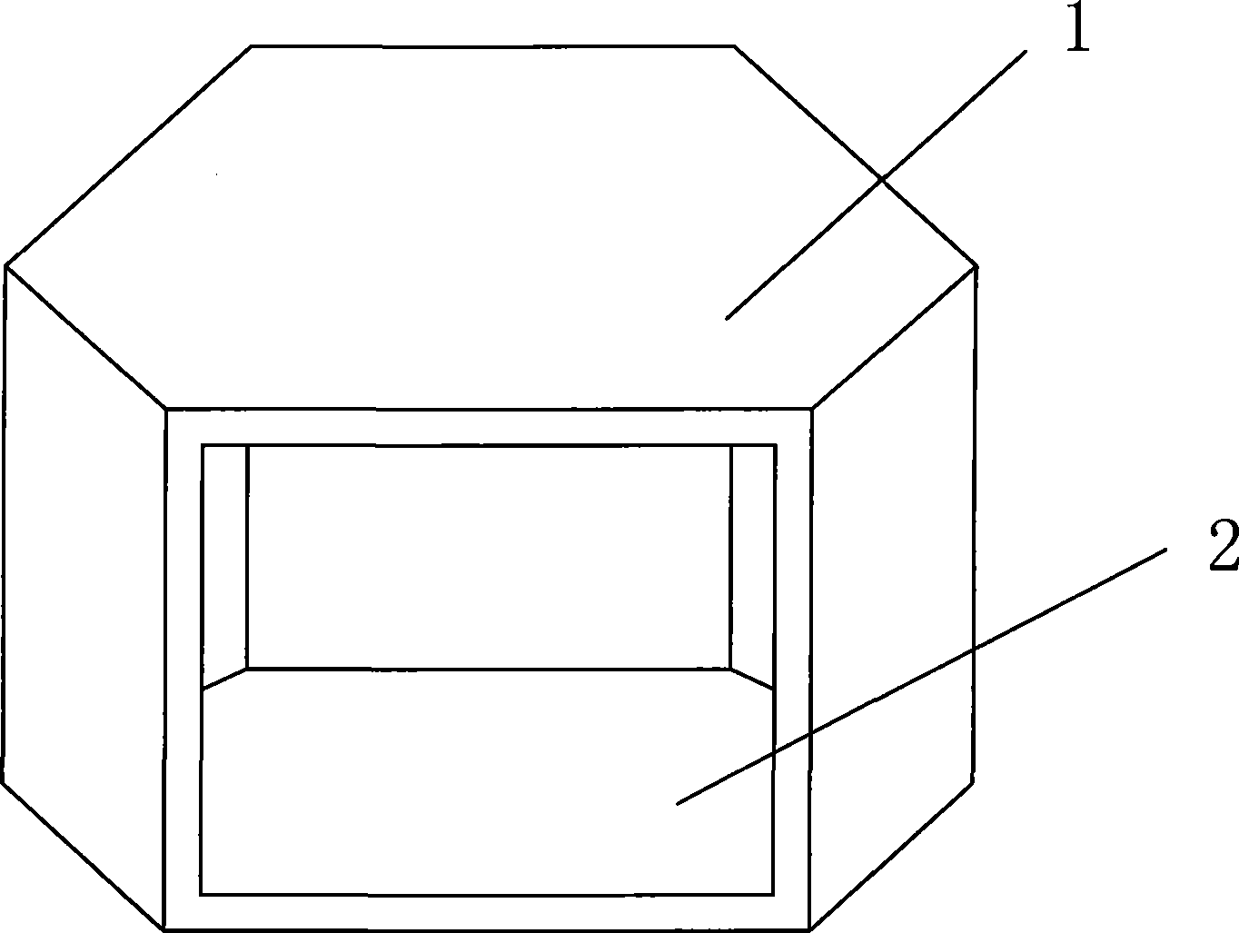
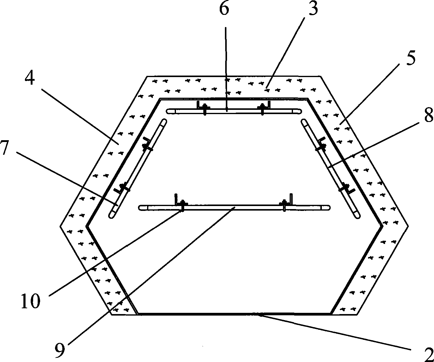
[0017] refer to figure 1 , figure 2 , The heat-absorbing cavity 1 is in the shape of a hexagonal column, and a daylight opening 2 is provided on one side thereof. The shell of the heat-absorbing cavity 1 is made of 304 steel plates, and the outside of the shell is wrapped with an insulating layer except the daylighting opening 2 . On the opposite side of the daylight opening 2 are the rear side wall 3, the left rear side wall 4 and the right rear side wall 5 of the heat-absorbing cavity 1. Boiling tubes 6, 7, 8 on the rear side, left rear side, and right rear side, and an overheating pipe 9 is arranged between the daylight opening 2 and the rear side wall 3.

[0018] The height of the daylighting opening 2 is relatively small, and the height of the wall directly behind the daylighting opening 2 is relatively large. The entire heat-absorbing cavity 1 is in a shape that gradually expands from the daylighting opening 2 to the rear. Boiling tubes 6, 7, 8 and overheating tube 9...


PUM


Abstract

The invention relates to the field of tower type solar heat power generation research, discloses a simulation device for a solar cavity type heat absorber, and is applicable to a simulation performance test of a cavity type heat absorber in the tower type solar heat power generation system. The simulation device comprises a drum and a hexagonal prism shaped heat absorbing cavity, wherein a side surface of the heat absorbing cavity is provided with a daylight opening; a dead backside wall, a left backside wall and a right backside wall of the heat absorbing cavity are arranged opposite to the daylight opening; a dead backside boiling tube, a left backside boiling tube and a right backside boiling tube are respectively arranged close to the dead backside wall, the left backside wall and the right backside wall; a superheat tube is arranged between the daylight opening and the dead backside wall; and the dead backside boiling tube, the left backside boiling tube, the right backside boiling tube and the superheat tube are respectively communicated with the drum. The simulation device is characterized in that the dead backside boiling tube, the left backside boiling tube, the right backside boiling tube and the superheat tube are made of stainless steel pipe coils which are directly heated by a power supply.

Description

technical field [0001] The invention relates to the research field of tower-type solar thermal power generation, in particular to a simulation device of a solar cavity heat absorber, which is suitable for the simulation test of the performance of the cavity type heat absorber in a tower-type solar thermal power generation system. Background technique [0002] Solar thermal power generation technology uses an optical system to gather solar radiation energy to heat the working medium to generate steam, which drives a steam turbine generator set to generate electricity. According to different concentrating methods, solar thermal power generation can be divided into: tower solar thermal power generation, trough solar thermal power generation and dish solar thermal power generation. At present, trough solar thermal power generation has been commercialized, while tower solar thermal power generation and dish solar thermal power generation are still mostly in the experimental and d...

Claims


Application Information

Patent Timeline
Patent Type & Authority Applications(China)
IPC IPC(8): G01M19/00G01M99/00
Inventor 郭烈锦魏进家张西民王跃社方嘉宾
Owner XI AN JIAOTONG UNIV
Why Eureka
Try Eureka