Surroundings control system and method for medical equipment

A technology for control systems and medical equipment, applied in general control systems, control/regulation systems, program control, etc., can solve problems such as high development costs, large control spans, and long development cycles, and achieve cost reduction and design and development time , meet different needs, and reduce workload

Inactive Publication Date: 2009-08-12
SIEMENS SHANGHAI MEDICAL EQUIP LTD
View PDF0 Cites 7 Cited by
  • Summary
  • Abstract
  • Description
  • Claims
  • Application Information

AI Technical Summary

Problems solved by technology

[0006] First, the circuit uses a CPLD, 2 D / A converters and an A / D converter. Due to the large number of modules, the circuit is more complicated and the cost is relatively high
[0007] Second, although the circuit can realize different hardware configurations by using CPLD to expand the interface of the microcontroller, but because the function of the environmental control system is relatively simple, and the CPLD has a large number of interfaces, most of the interfaces of the CPLD have not been obtained. Fully utilized, resulting in a waste of CPLD use
[0008] Third, the use of CPLD requires developers to compile software by themselves, so the software development cost is high and the development cycle is long
[0009] Fourth, at present, 3-level control is used for the control of LED lighting equipment and fan speed regulation. The control span between each level is large, and different patients have different requirements for lighting and ventilation under different circumstances. CPLD control is used It is difficult for the circuit to meet the requirements of different patients

Method used


Image

  • Surroundings control system and method for medical equipment
  • Surroundings control system and method for medical equipment
  • Surroundings control system and method for medical equipment

Examples


Embodiment Construction

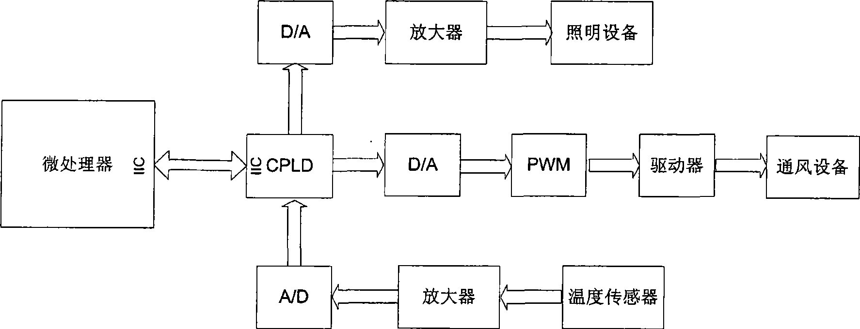
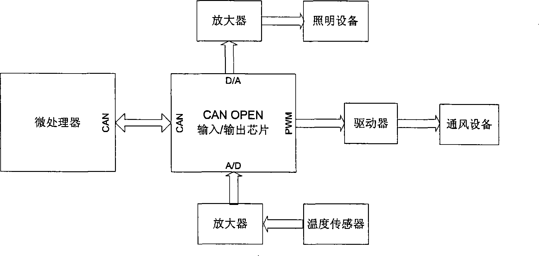
[0034] figure 2 It is a schematic diagram of the environmental control system on the medical equipment in the present invention. The environmental control system includes a figure 2 The medical device controller on the left, two devices to be controlled, and one monitoring device. The two devices to be controlled are LED lighting equipment and a fan respectively. One monitoring device is a temperature monitor.

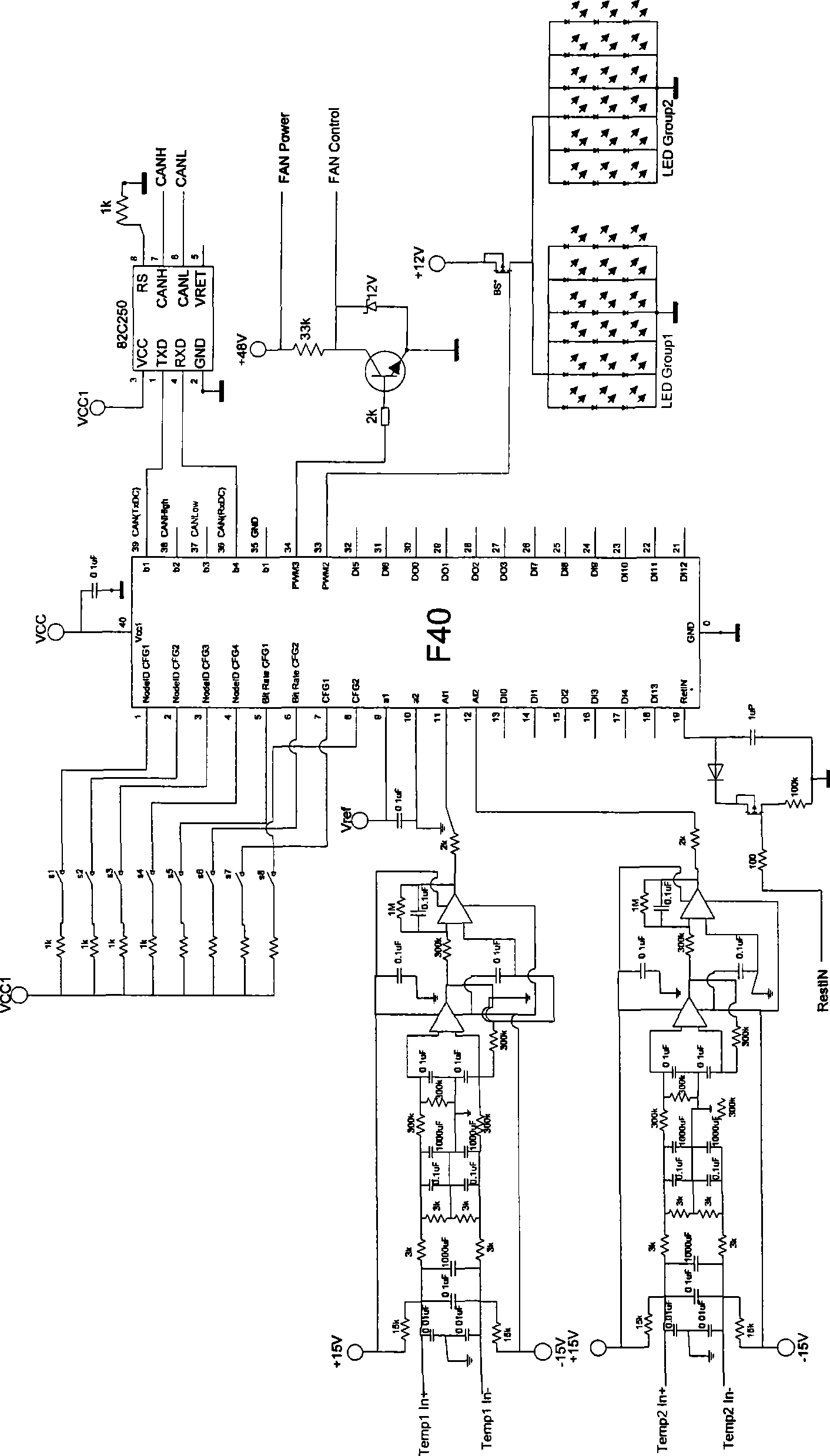
[0035] According to the present invention, the environmental control system on the medical equipment also includes a CAN input / output module, and the medical equipment controller controls the lighting of the LED lighting equipment, controls the air volume of the fan and / or monitors the temperature from the CAN input / output module. The device obtains temperature information. Specifically, the CAN input / output module (or called CANopen input / output chip) is a chip based on the DS401 protocol, which integrates a D / A converter, an A / D converter and a PWM generator in...


PUM


Abstract

The invention discloses an environment control system, which comprises a medical equipment controller, and at least one device to be controlled or a monitoring device. The environment control system also comprises a CAN input / output module, wherein the medical equipment controller controls the device to be controlled through the CAN input / output module or acquires monitoring information from the monitoring device. The CAN input / output module drives the device to be controlled through a digital / analog converter or a pulse-width modulation generator; or the monitoring information of the monitoring device is input to the CAN input / output module through one digital / analog converter. The environment control system adopts the CAN input / output module to perform signal transmission, the CAN input / output module serves as an independent node and becomes a system to achieve modularization, and the cost is reduced from the view point of hardware.

Description

technical field [0001] The invention relates to an environment control system and method, in particular to an environment control system and method in medical equipment. Background technique [0002] In some medical equipment, such as MRI equipment, due to the small inner diameter of the magnet and the long distance between the front and rear ends, the light inside the magnet is dark, the air circulation is slow, and the temperature changes quickly during the examination. In order to make the patient have a more comfortable environment and reduce psychological stress when being examined, it is necessary to add a lighting system and a ventilation system inside the magnet, and to monitor the ambient temperature around the patient. [0003] In the prior art, the environmental control system of the nuclear magnetic resonance equipment is such as figure 1 shown. figure 1 Among them, on the one hand, the microcontroller sends control signals to the complex programmable logic dev...

Claims


Application Information

Patent Timeline
Patent Type & Authority Applications(China)
IPC IPC(8): G05B19/048
Inventor 田山郭灿
Owner SIEMENS SHANGHAI MEDICAL EQUIP LTD
Why Eureka
Try Eureka