Liquid crystal display apparatus

A liquid crystal display device and pixel technology, applied in nonlinear optics, instruments, optics, etc., can solve the problems of reduced pixel aperture ratio and overall brightness reduction

Active Publication Date: 2009-08-12
SHARP KK
View PDF1 Cites 12 Cited by
  • Summary
  • Abstract
  • Description
  • Claims
  • Application Information

AI Technical Summary

Problems solved by technology

However, by providing the notch on the pixel electrode 10 in this way, the ...

Method used


Image

  • Liquid crystal display apparatus
  • Liquid crystal display apparatus
  • Liquid crystal display apparatus

Examples


Embodiment approach 1

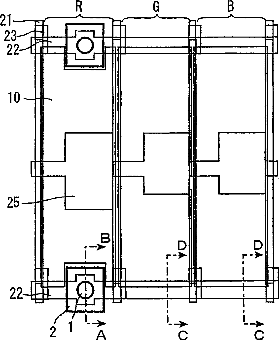
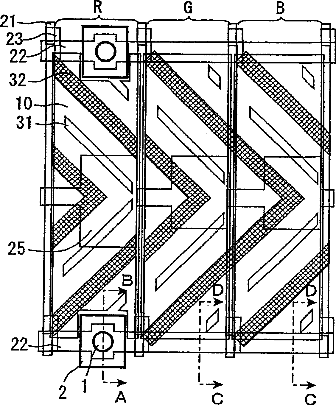
[0067] figure 1 It is a schematic plan view showing red, green, and blue pixels of the liquid crystal display device according to the first embodiment. The liquid crystal display device of this embodiment has a structure in which an array substrate and a color filter substrate face each other with a liquid crystal layer interposed therebetween, and is driven by an active matrix method.

[0068] Such as figure 1 As shown, on the array substrate, the source wiring (signal line) 21 and the gate wiring (scanning line) 22 are arranged along the vertical and horizontal directions. ) near the portion, a TFT 23 as a switching element is disposed. The pixel electrode 10 made of ITO or the like is formed so as to be surrounded by the source wiring 21 and the gate wiring 22 . The pixel electrode 10 is electrically connected to the drain electrode of the TFT 23 through a contact hole. Furthermore, storage capacitor wiring (Cs wiring) 25 is formed parallel to the gate wiring 22 so as...


PUM


Abstract

A liquid crystal display apparatus that in the formation of columnar spacer, realizes enhancement of brightness. The liquid crystal display apparatus is one comprising a pair of substrates and, interposed therebetween, a liquid crystal layer and having red, green and blue pixels, wherein among three pixels of red, green and blue, the red pixel is provided with a columnar spacer structure, and wherein the aperture ratio of the red pixel is smaller than those of the green and blue pixels.

Description

technical field [0001] The present invention relates to a liquid crystal display device. More specifically, it relates to a liquid crystal display device including a columnar spacer as a cell for maintaining a cell gap. Background technique [0002] Liquid crystal display devices display by controlling the optical characteristics of light emitted from a light source by using a liquid crystal layer filled in a liquid crystal display panel, and are used in various fields by utilizing features such as thinness, light weight, and low power consumption. A liquid crystal display panel, which is a main part of such a liquid crystal display device, generally has a structure in which a liquid crystal layer is sandwiched between a pixel array substrate and a color filter substrate, and the thickness of the liquid crystal layer is maintained by a spacer arranged between the substrates. (unit gap). As the spacer, for example, a spherical spacer made of plastic or an inorganic material...

Claims


Application Information

Patent Timeline
IPC IPC(8): G02F1/1339G02F1/13357G02F1/1335G02F1/1343
CPCG02F1/13394G02F1/133514G02F2201/40
Inventor 逸见郁未下敷领文一川端雅江
Owner SHARP KK
Why Eureka
Try Eureka