
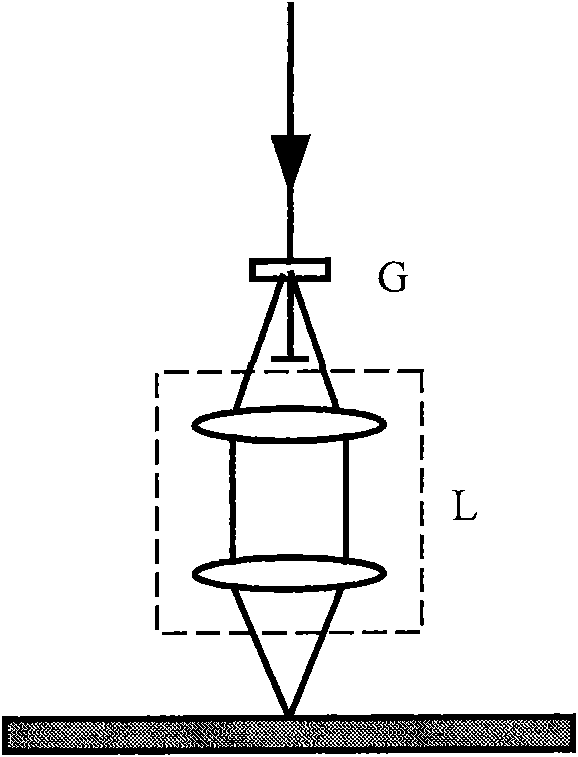
Optical lens for ultraviolet laser interference photolithography straight-writing system

An ultraviolet laser and optical lens technology, applied in microlithography exposure equipment, optics, optical components, etc., can solve the problem of impossible to make sub-micron structure patterns, and achieve the goal of reducing aberration, improving imaging quality, and reducing the number of lenses. Effect

Active Publication Date: 2010-10-20
SUZHOU UNIV +1
View PDF1 Cites 0 Cited by
  • Summary
  • Abstract
  • Description
  • Claims
  • Application Information

AI Technical Summary

Problems solved by technology

[0004] Using the laser direct writing system, generally only microstructures larger than 1000nm can be produced. Under the current conditions, it is impossible to produce submicron structure patterns.

Method used


Image

  • Optical lens for ultraviolet laser interference photolithography straight-writing system
  • Optical lens for ultraviolet laser interference photolithography straight-writing system
  • Optical lens for ultraviolet laser interference photolithography straight-writing system

Examples


Embodiment 1

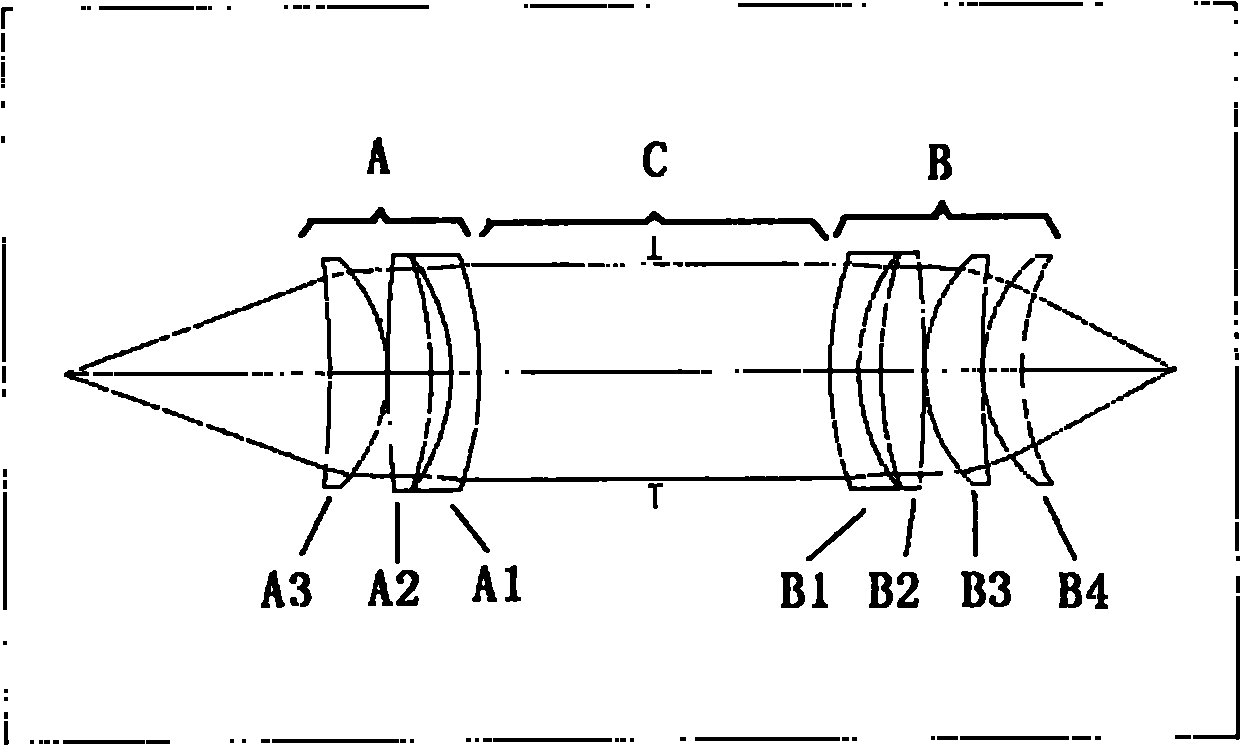
[0033] Such as figure 2 As shown, the ultraviolet interference lens is composed of two groups of seven lenses consisting of object-side lens group A and image-side lens group B. The two groups of lenses form a bi-telecentric optical system. The distance between the two groups of lenses can be changed to achieve focusing. Features. Group A lens is composed of three lenses A3, A2, A1, and group B lens is composed of four lenses B1, B2, B3, B4. The optical materials are all fused silica (SILICA) with high transmittance in the ultraviolet band. The propagation directions are A3, A2, A1, B1, B2, B3, and B4 in sequence; among them, A1, B1 are meniscus concave lenses, A2, B2 are biconvex lenses, and A3, B3, B4 are meniscus convex lenses.

[0034] The structural data of the interference lens are as follows (unit: mm):

[0035] serial number

radius

spacing

Material

caliber

Object surface

36.968

Air

1

-145.55

8

Fu...

Embodiment 2

[0042] attached Figure 10 It is the structure diagram of the second embodiment of the ultraviolet interference lens of the present invention, and at a wavelength of 355nm, the object-side numerical aperture reaches 0.55.


PUM

PropertyMeasurementUnit
refractive indexaaaaaaaaaa

Abstract

The invention discloses an optical lens which is used for an ultraviolet laser interference lithography direct writing system, being characterized in that the optical lens consists of an object space lens group A and an image space lens group B; the lens group A consists of three pieces of lens: A3, A2 and A1, and the lens group B consists of four pieces of lens: B1, B2, B3 and B4; the light propagation direction is A3, A2, A1, B1, B2, B3, and B4 in sequence; and wherein, A1 and B1 are meniscus-type concave lenses, A2 and B2 are double convex lenses, and A3, B3 and B4 are meniscus-type convexlenses. The image space lens of the invention adopts a four-piece structure design; therefore, the numerical aperture thereof is large, and the structure of the interference fringes is fine; by limiting the object space numerical aperture, the number of lenses can be decreased, the accumulated process error in actual processing can be reduced, and the coordination with the diffraction grating of an interference lens object space is easy; and the manufacture of a sub-wavelength structure can be realized on the laser interference direct writing system.

Description

technical field [0001] The invention relates to an interference optical component, in particular to a structure of an optical lens with a submicron structure produced by laser interference, and belongs to the field of micro-nano structure manufacturing. Background technique [0002] Subwavelength optics is a current research hotspot. Due to its microstructure in the subwavelength scale (50-400nm), subwavelength optical devices exhibit optical characteristics that general diffractive optical elements do not have, such as narrow spectral band, polarization, light guide, Surface anti-reflection and other properties, the sub-wavelength structure is convenient and has application value in improving the light extraction efficiency of OLED. For visible light, the sub-wavelength structure generally has a scale below 400nm, which can only be achieved by ultra-fine processing methods. The most typical methods are e-beam lithography and UV projection lithography. lithography). [000...

Claims


Application Information

Patent Timeline
Patent Type & Authority Patents(China)
IPC IPC(8): G03F7/20G02B13/00
Inventor 浦东林陈林森魏国军周小红
Owner SUZHOU UNIV
Learn More