Check patentability & draft patents in minutes with Patsnap Eureka AI!

Oscillating mirror correcting system and correcting method thereof

A technology of correction system and correction plate, which is applied in the direction of lenses, instruments, laser welding equipment, etc., can solve the problems of high cost, correction, time-consuming and inability to galvanometer, etc., and achieve the effect of rapid correction

Inactive Publication Date: 2009-08-26
HANS LASER TECH IND GRP CO LTD +1
View PDF0 Cites 58 Cited by
  • Summary
  • Abstract
  • Description
  • Claims
  • Application Information

AI Technical Summary

Problems solved by technology

[0004] The purpose of the embodiments of the present invention is to provide a galvanometer calibration system, which aims to solve the problem that the existing galvanometer calibration system needs to use auxiliary measurement equipment, which leads to high cost, time-consuming, and the problem that the galvanometer cannot be calibrated at any time

Method used


Image

  • Oscillating mirror correcting system and correcting method thereof
  • Oscillating mirror correcting system and correcting method thereof
  • Oscillating mirror correcting system and correcting method thereof

Examples


Embodiment Construction

[0020] In order to make the object, technical solution and advantages of the present invention clearer, the present invention will be further described in detail below in conjunction with the accompanying drawings and embodiments. It should be understood that the specific embodiments described here are only used to explain the present invention, not to limit the present invention.

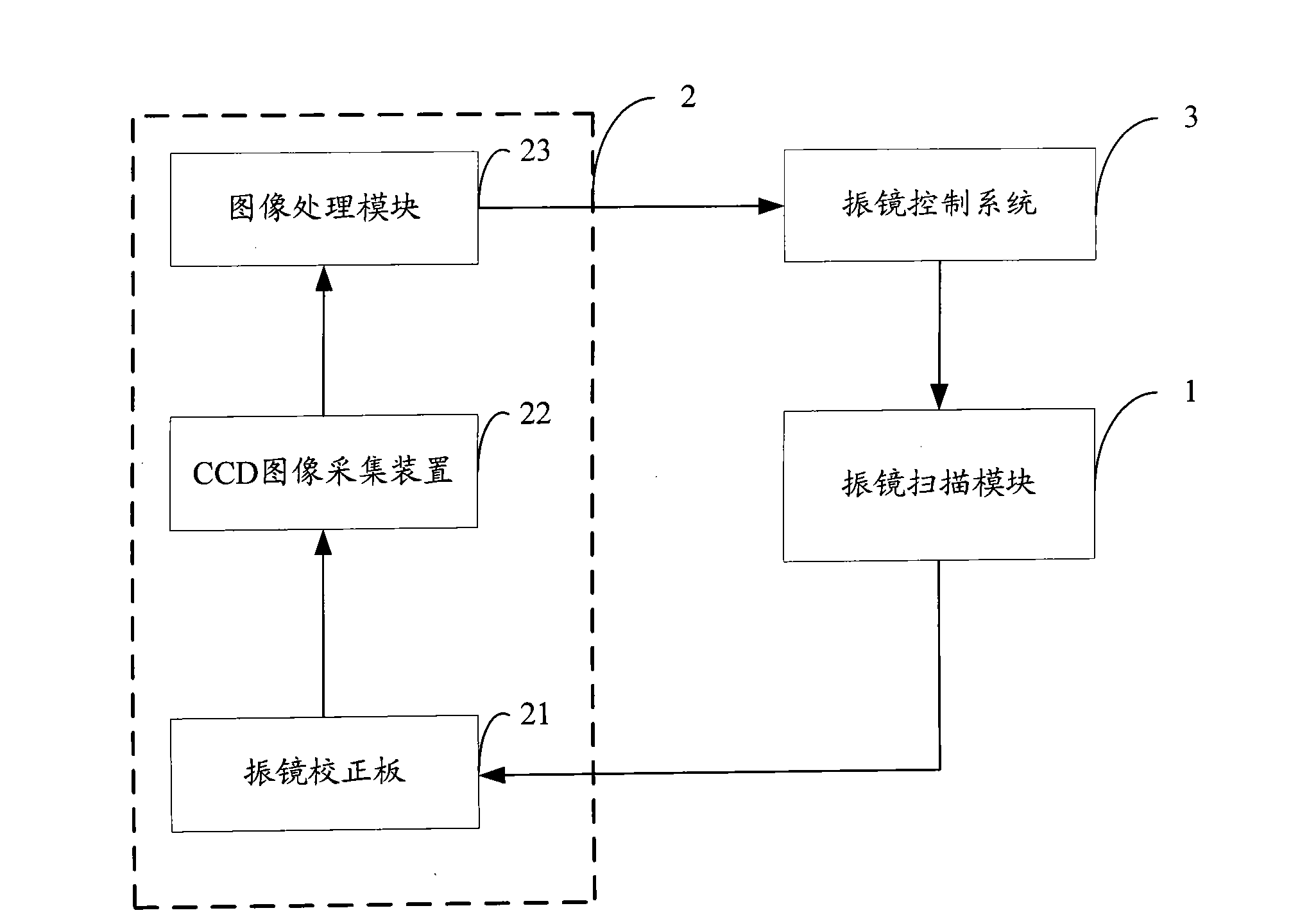
[0021] The galvanometer correction system provided by the embodiment of the present invention adopts a charge coupled device (Charge Coupled Device, CCD) image acquisition device to perform image acquisition on the matrix target on the galvanometer correction board, and processes the acquired matrix target through the image processing module Then output the compensation file of the galvanometer to calibrate the galvanometer; the correction of the galvanometer can be realized simply, conveniently and quickly without the aid of auxiliary equipment.

[0022] figure 1 The module structure of the galva...


PUM


Abstract

The present invention is suitable for the technical field of laser processing, and provides an oscillating mirror correcting system and a correcting method thereof. The oscillating mirror correcting system comprises the following components: an oscillating mirror correcting plate which is formed with a matrix target through controlling laser by an oscillating scanning module; a CCD image collector which is used for executing image collection to the rectangular target on the oscillating mirror correcting plate; and an image processing module which is used for outputting an oscillating mirror compensation file for correcting the oscillating mirror after the matrix target collected by the CCD image collector is processed. The oscillating mirror correcting system provided by the invention adopts the CCD image collector for executing image collection to the matrix target on the oscillating mirror correcting plate and outputs the oscillating compensation file for correcting the oscillating mirror after the collected matrix target is processed through the image processing module. The correction to oscillating mirror can be realized simply, conveniently and quickly without an auxiliary device.

Description

technical field [0001] The invention belongs to the technical field of laser processing, and in particular relates to a vibrating mirror correction system and a correction method thereof. Background technique [0002] In laser processing technology, the galvanometer is generally used to control the optical path to process various complex graphics and characters; due to interference, motor lost steps, etc., the galvanometer will deviate after a certain period of time, resulting in There is a deviation between the area scanned by the galvanometer and the interface between the areas. At this time, error compensation should be performed on the galvanometer to reduce this deviation. [0003] The traditional technology is to make a matrix target on the calibration board, and then combine with auxiliary measuring equipment (such as the second element, etc.) to measure, manually calculate the deviation between theory and reality, and then generate a calibration file through compensa...

Claims


Application Information

Patent Timeline
IPC IPC(8): B23K26/42G02B3/00B23K26/70
Inventor 高云峰翟学涛胡福原雷群
Owner HANS LASER TECH IND GRP CO LTD
Features
  • R&D
  • Intellectual Property
  • Life Sciences
  • Materials
  • Tech Scout
  • Unparalleled Data Quality
  • Higher Quality Content
  • 60% Fewer Hallucinations
Learn More