High-speed railway and wheel-rail train

A high-speed rail and train technology, applied in the field of rail transportation, can solve the problems of high-speed stability and reliability taking a long time, incompatibility with each other to connect the transportation network, pantograph and catenary wear, etc., to shorten the construction time. , the structure is simple, the effect of reducing the cost of infrastructure construction

Inactive Publication Date: 2009-08-26
李葛亮
View PDF0 Cites 10 Cited by
  • Summary
  • Abstract
  • Description
  • Claims
  • Application Information

AI Technical Summary

Problems solved by technology

[0004] In the traditional wheel-rail railway, the traction, guiding force and supporting force obtained by the vehicle are all obtained by the interaction between the wheel and the rail. The traction power of the locomotive comes from the traditional rotating motor. The disadvantages of the traditional electrified railway are: 1. Electric locomotives The pantograph and catenary need to be repaired and replaced frequently due to wear and tear; 2. The adhesion coefficient between the wheel and rail decreases with the increase of the train speed, but the running resistance increases with the increase of the train speed. When the speed increases to the adhesion coefficient When the intersection point of the curve and the walking resistance curve, the limit is reached
The main disadvantages of maglev transportation are: 1. Since the maglev system realizes the suspension, guidance and driving functions by electromagnetic force, the safety guarantee measures for maglev after power failure, especially the braking problem of the train after power failure is still a problem to be solved. Its high-speed stability and reliability still need to be tested for a long time; 2. The maglev track in the above system is completely different from the traditional wheel-rail railway in terms of driving, supporting (suspension), guiding and turnout, and the technology used is completely different , so they cannot be compatible with each other to form a transportation network, and can only be applied to point-to-point transportation, and the infrastructure cost is high

Method used


Image

  • High-speed railway and wheel-rail train
  • High-speed railway and wheel-rail train
  • High-speed railway and wheel-rail train

Examples


Embodiment 2

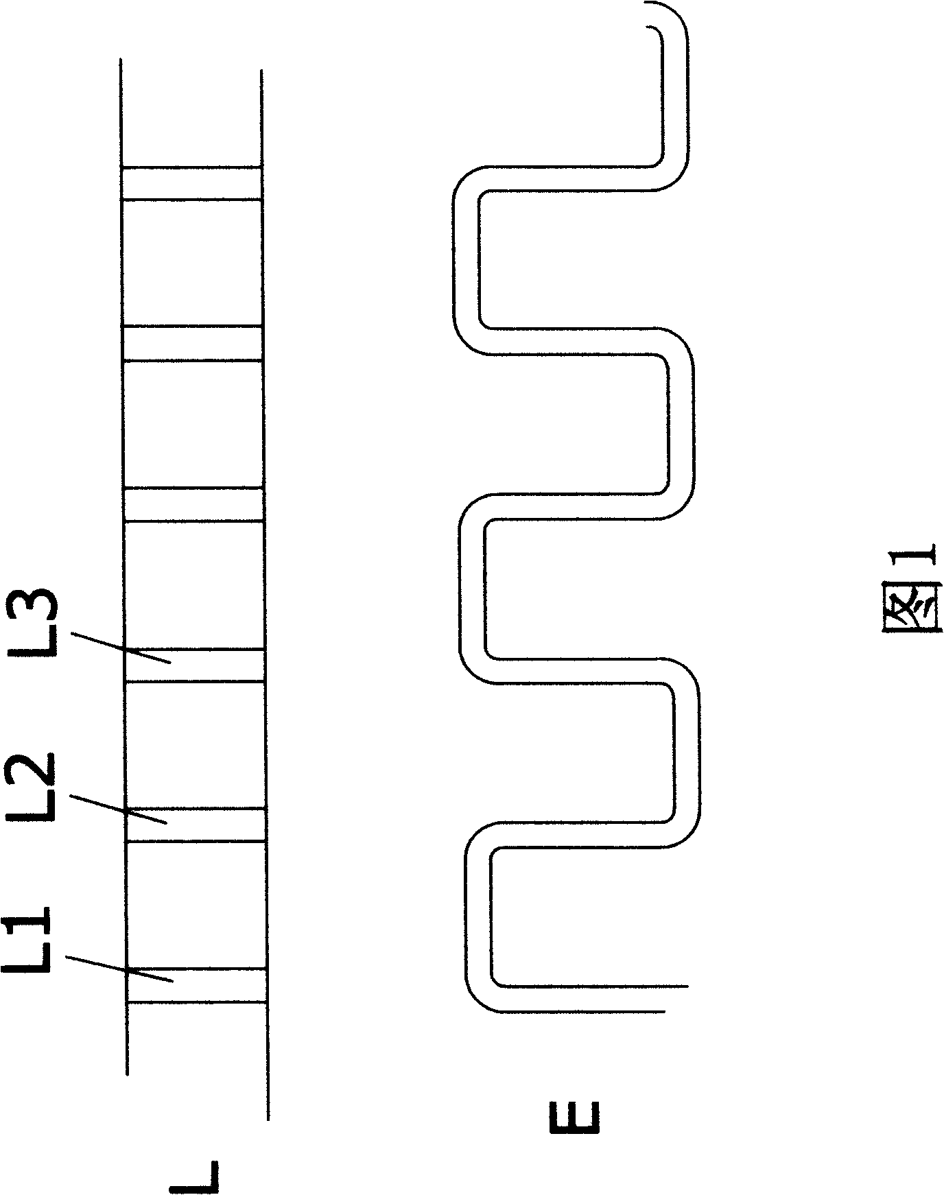
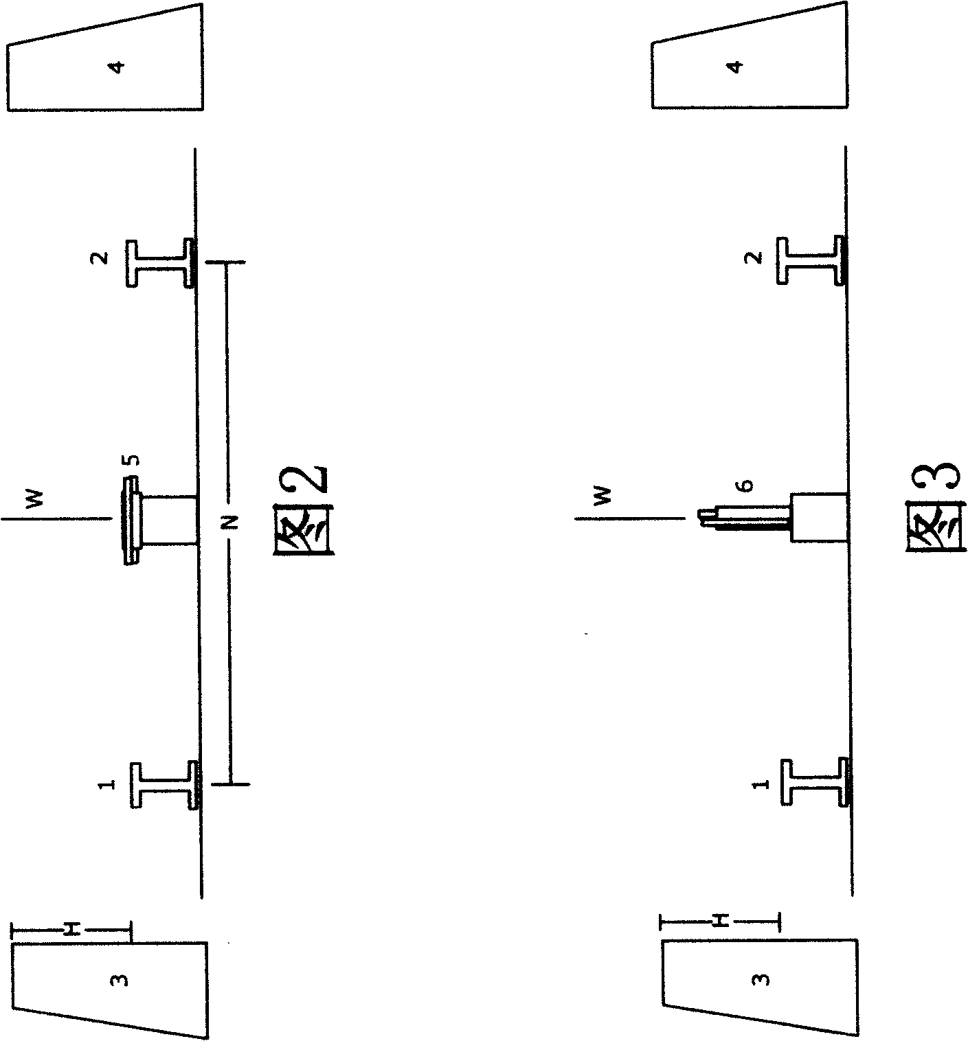
[0046] A preferred high-speed rail implementation such as image 3 shown. A plurality of winding supports (L) arranged in a row having slots (L1, L2, L3...) substantially equidistant from one another perpendicular to the longitudinal direction, the wires of at least two linear motors being elongated in a zigzag shape The stator winding (E) is partly arranged in the slots (L1, L2, L3...) of the winding support (L) to form a long stator track (6). There is a long stator track (6) in the high-speed track The middle part between the metal rails (1, 2). The virtual plane (W) is the plane of symmetry of the two metal rails (1, 2), which is not a physical plane, and the slots (L1, L2, L3...) on the long stator track (6) are basically parallel to the plane of symmetry (W). Long stator windings (E) and winding supports (L) see figure 1 .

Embodiment 3

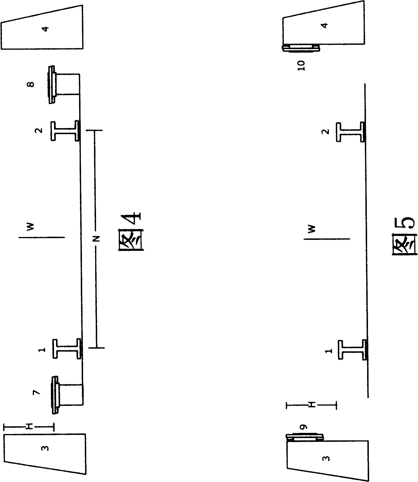
[0048] A preferred high-speed rail implementation such as Figure 4 shown. A plurality of winding supports (L) arranged in a row having slots (L1, L2, L3...) perpendicular to the longitudinal direction and substantially equidistant from each other, at least one wire of a linear motor in a zigzag shape around a long stator Windings (E), and partly arranged in the slots (L1, L2, L3...) of the winding support (L) to form long stator tracks (7, 8). The virtual plane (W) is the symmetric plane of the two metal rails (1, 2), which is not a physical plane. There are two long stator rails (7, 8) in the high-speed rail which are basically symmetrical with respect to the virtual plane (W). The slots (L1, L2, L3...) on the long stator rails (7, 8) are substantially perpendicular to the imaginary plane (W). Figure 4 (7, 8) is the outer side close to (1, 2), and may also be the inner side close to (1, 2). Long stator windings (E) and winding supports (L) see figure 1 .

[0049] High-...


PUM


Abstract

The invention discloses a high-speed railway and a wheel-rail train, which belong to the technical field of track traffic. The high-speed railway is basically characterized in that electric wires of a linear motor are used to substitute a contact net so as to reduce the maintenance work needed by the contact net due to the abrasion; and the safety of the peripheries of the train and the railway is ensured through concrete side rails. The wheel-rail train is basically characterized in that: the train ensures that train wheels and ferromagnetic metal rails do not break away from each other through the mutual attraction of attraction magnets and the metal rails to ensure the safety of the train during high-speed driving. The dispersed arrangement of rotor magnets on the train makes the power dispersed, and the working electric power used on the train comes from a generator driven by the partial train wheels which roll on the wheel rails during the driving. The high-speed railway and the wheel-rail train are novel track traffic technology which is between wheel rail technology and magnetic suspension technology, integrates the advantages of the wheel rail technology and the magnetic suspension technology, is superior to the wheel rail technology and the magnetic suspension technology, and have the advantages of safety, high speed, environmental protection, and the like.

Description

technical field [0001] The invention belongs to the field of rail transportation, specifically including high-speed rails and wheel-rail trains. Background technique [0002] The world's first electrified railway was laid by Germany's Siemens and Halsk at the Berlin Trade Fair in 1879. It is 300 meters long and has a gauge of 1000 mm. Since then, with the development of science and technology, the growth of railway traffic and the emphasis on energy efficiency, the operating mileage of electrified railways around the world has increased year by year. An electrified railway is composed of an electric locomotive and a traction power supply device. The electric locomotive itself does not carry energy, but is supplied with electric energy by an external power system through the traction power supply device. The traction power supply device is generally divided into two parts: the traction substation and the catenary, so the electric locomotive, the traction substation and the c...

Claims


Application Information

Patent Timeline
Patent Type & Authority Applications(China)
IPC IPC(8): B60L13/03B60M3/00
Inventor 李葛亮
Owner 李葛亮
Why Eureka
Try Eureka