Turning hoisting method for vertical type apparatus

A hoisting method and technology of vertical equipment, applied in transportation and packaging, load hanging components, cranes, etc., can solve the problems of high cost of foundation treatment, and achieve the effects of simple anti-tilt facilities, convenient operation, and wide application range

Active Publication Date: 2009-08-26
SINOPEC NINGBO ENG
View PDF1 Cites 16 Cited by
  • Summary
  • Abstract
  • Description
  • Claims
  • Application Information

AI Technical Summary

Problems solved by technology

Since the crane needs to walk during the hoisting process, it is necessary to deal with the foundation of the crane, and the cost of foundation treatment is relatively high

Method used


Image

  • Turning hoisting method for vertical type apparatus
  • Turning hoisting method for vertical type apparatus
  • Turning hoisting method for vertical type apparatus

Examples


Embodiment 1

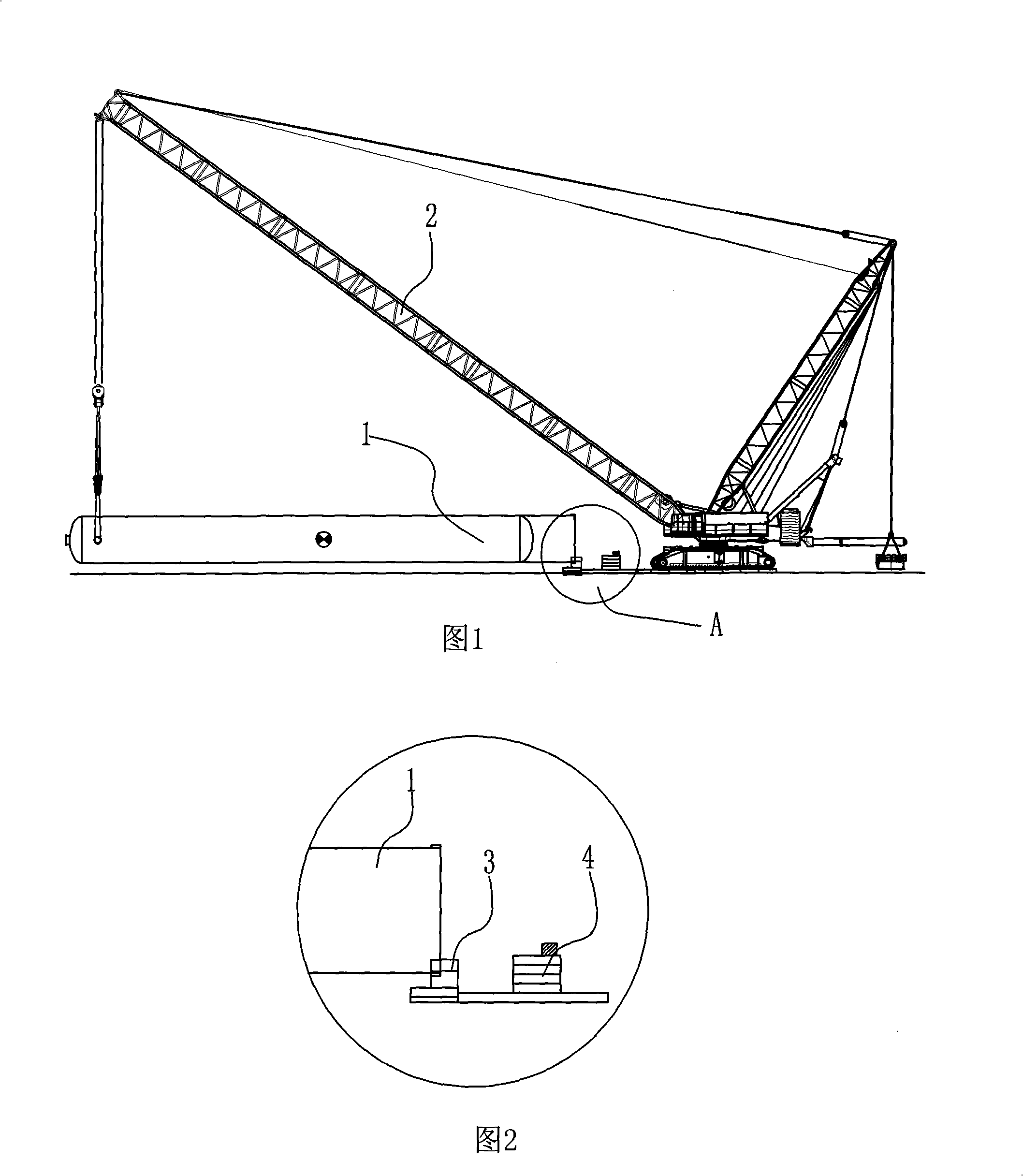
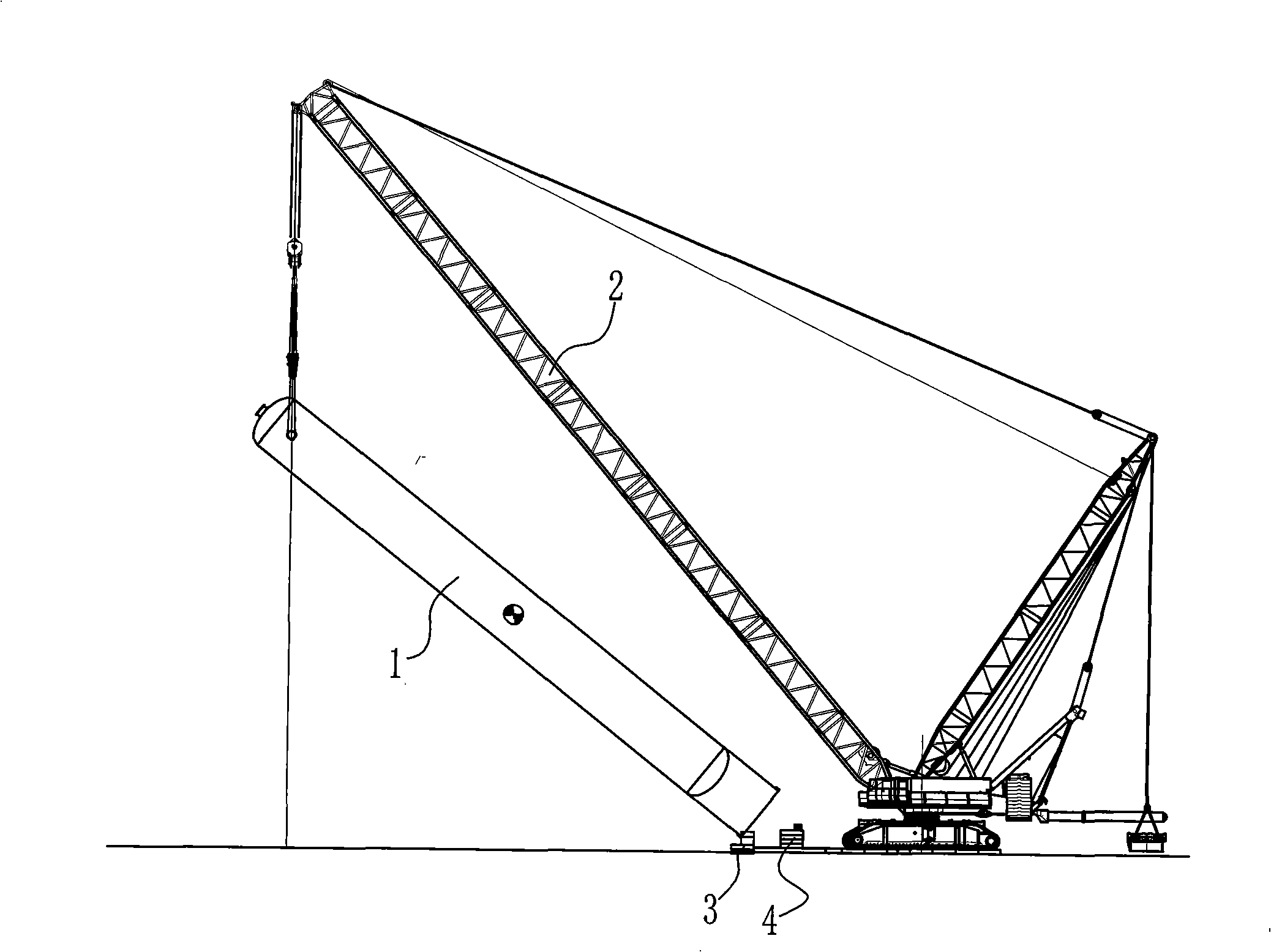
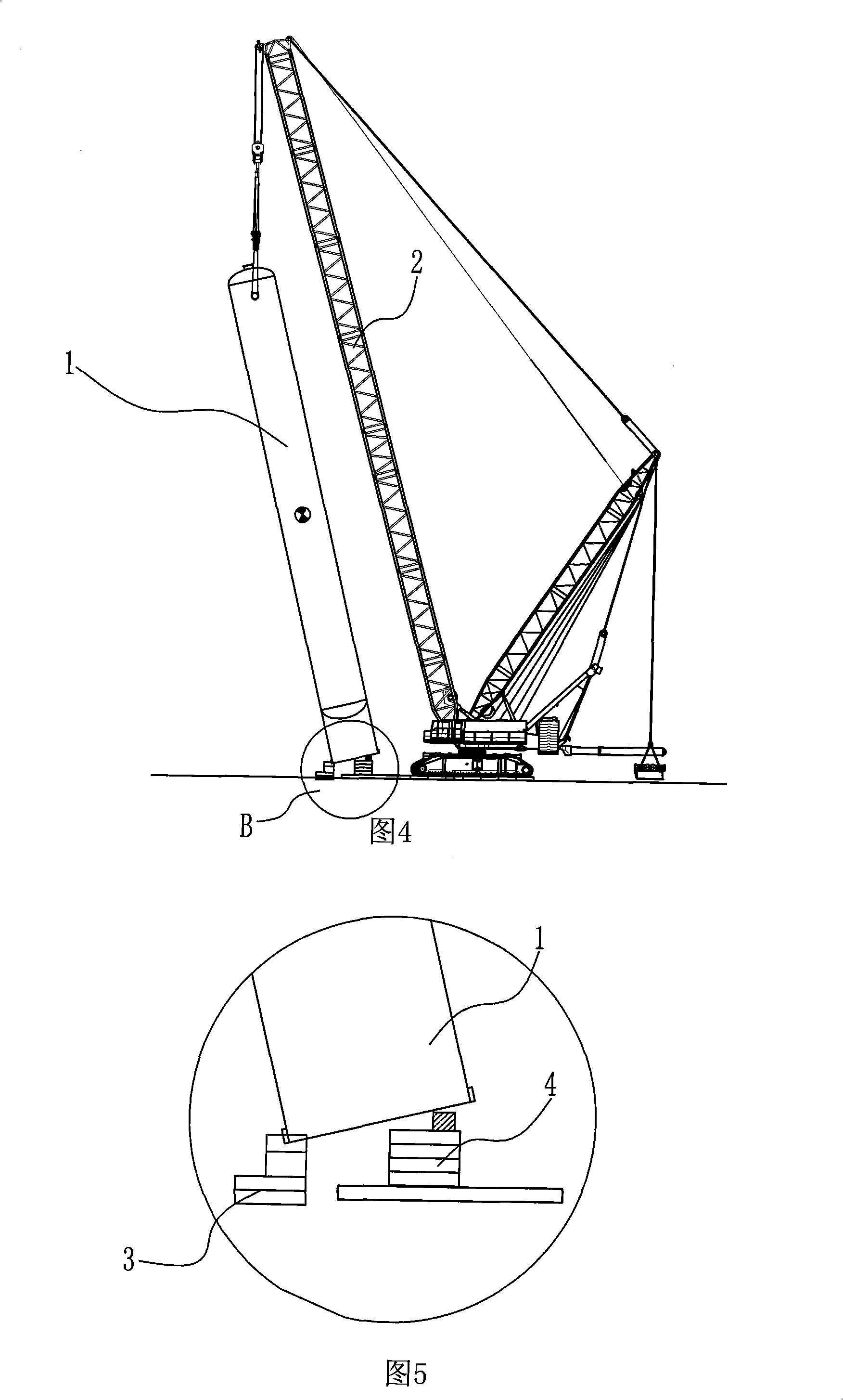
[0046] First set the rotating shaft system 3 and the anti-tilt facility 4, such as figure 1 and figure 2 shown. The rotating shaft system 3 can be the rotating shaft system in the current turning method, pushing method and rolling tail method, and can also be a rotating shaft system developed for this hoisting process. This embodiment adopts the rotating shaft system developed for this hoisting process. Firstly, an underground foundation 31 is installed underground. The turntable 38 is circular and includes an upper turntable and a lower turntable, the lower turntable is fixed on the chassis 32, the lower turntable is fixed on the carrier plate 33 above it, and the upper turntable and the lower turntable are formed by bearing connection A matching structure that can rotate around the vertical axis of rotation 36. Two horizontal shaft bearings 34 are fixedly installed on the bearing plate 33, and a shaft hole 39 is formed on the top of the horizontal shaft bracket 34, and t...

Embodiment 2

[0050] This embodiment is only different from the embodiment in the shaft system used, and the others are the same as embodiment 1.

[0051] The present embodiment adopts the more commonly used rotating shaft system and anti-tilt facilities in the crane rolling tail in the conventional technology. First be provided with as the platform 5 for placing the rotating shaft system 6 and the anti-tilt facility 7. Platform 5 can use the subgrade box of crane to lay and form, and this platform 5 can be connected with the subgrade box under the crawler belt of crane, and platform 5 is fixed by the gravity of crane self. A rotating shaft system 6 is set at the end of the platform 5 away from the crane, and an anti-tilt facility 7 is set at the end of the platform 5 close to the crane. The rotating shaft system 6 is composed of a roadbed box 63 , a rotating shaft base 62 and a rotating shaft 63 . The roadbed box 63 is welded and fixed with the platform 5, and the lower end of the rotati...


PUM


Abstract

The invention relates to a turning hoisting method for the vertical type apparatus, characterized by comprising the following steps: a) the apparatus to be hoisted is unloaded according to the hoisting site condition and the hoisting machine station, and the tail of the apparatus faces to the hoisting machine; b) a rotating shaft system is arranged near to the tail of the apparatus, and a falling preventing device is arranged at the position where the apparatus arrive in the falling preventing angle; c) the lift hook of the hoisting machine is connected with the lifting point of the apparatus, which is located above the center gravity of apparatus; d) the hoisting machine lifts the lift hook and extends the arm rod of the hoisting machine to rotate the apparatus around the rotating shaft system and lift the apparatus step by step: e) the tail of the apparatus contacts with the falling preventing device when the apparatus arrive in the falling preventing angle position, the hoisting machine continuously lifts the lift hook and extends the arm rod of the hoisting machine to rotate the apparatus around the falling preventing device until the apparatus is completely vertical; f) the hoisting machine continuously lifts the lift hook to make the apparatus disengaged from the falling preventing device, the rotating shaft is removed; g) the operation radius of the hoisting machine is adjusted to be the positioning radius, then the apparatus is rotated to the base, the orientation is adjusted to position the apparatus. The hoisting method provided by the invention has no pulley set, no limitation to the lifting point orientation and simple operation.

Description

technical field [0001] The invention relates to the field of hoisting, in particular to a turning hoisting method for vertical equipment. Background technique [0002] At present, for the hoisting of vertical equipment, the pushing method and the turning method are usually used. The current hoisting method using a mast or gantry requires welding of the upper and lower sets of lifting points before hoisting. Set rigging on both sides of the mast (mast) to connect the upper and lower sets of lifting points to form a lifting triangle. Set the sliding track of the mast (mast), and move the mast (mast) by tightening the traction pulley during the hoisting process so as to push the equipment to rotate around the rotating shaft set at the rear of the equipment until the equipment is completely upright. The vertical equipment is hoisted by the turning method, which also uses a gantry or mast. The gantry or mast connects the lifting point on the equipment with the equipment through ...

Claims


Application Information

Patent Timeline
Patent Type & Authority Applications(China)
IPC IPC(8): B66C13/08B66C23/36
Inventor 王志远鲍志渊石飞
Owner SINOPEC NINGBO ENG
Why Eureka
Try Eureka