Method for designing loading trajectory of airplane skin lengthwise stretch forming and generating numerical control codes

A technology for loading trajectory and aircraft skin, applied in digital control, position/direction control, electrical program control, etc., can solve the problem of lack, the precise control function of numerical control drawing equipment fails to play, and it is difficult to meet the production of new aircraft skin parts requirements, etc.

Inactive Publication Date: 2009-08-26
BEIHANG UNIV
View PDF0 Cites 13 Cited by
  • Summary
  • Abstract
  • Description
  • Claims
  • Application Information

AI Technical Summary

Problems solved by technology

In recent years, domestic aviation manufacturing enterprises have generally introduced advanced CNC stretch forming machines, which has established a good hardware environment for improving the level of skin manufacturing and product quality, but lacks the definition of loading trajectory and programming software for CNC stretch forming machines that match the equipment. As well as the supporting process parameter design and optimization comparison solutions, generally the process program and parameters are roughly determined through repeated trial and error, and the final production process plan is determined by manual control or only by using the teaching function of the CNC drawing equipment
This makes the precise control function of the numerical control stretching equipment for deformation unable to play, it is difficult to meet the production requirements of new aircraft skin parts, and it also seriously restricts the improvement of the overall level of my country's aircraft manufacturing

Method used


Image

  • Method for designing loading trajectory of airplane skin lengthwise stretch forming and generating numerical control codes
  • Method for designing loading trajectory of airplane skin lengthwise stretch forming and generating numerical control codes
  • Method for designing loading trajectory of airplane skin lengthwise stretch forming and generating numerical control codes

Examples


Embodiment Construction

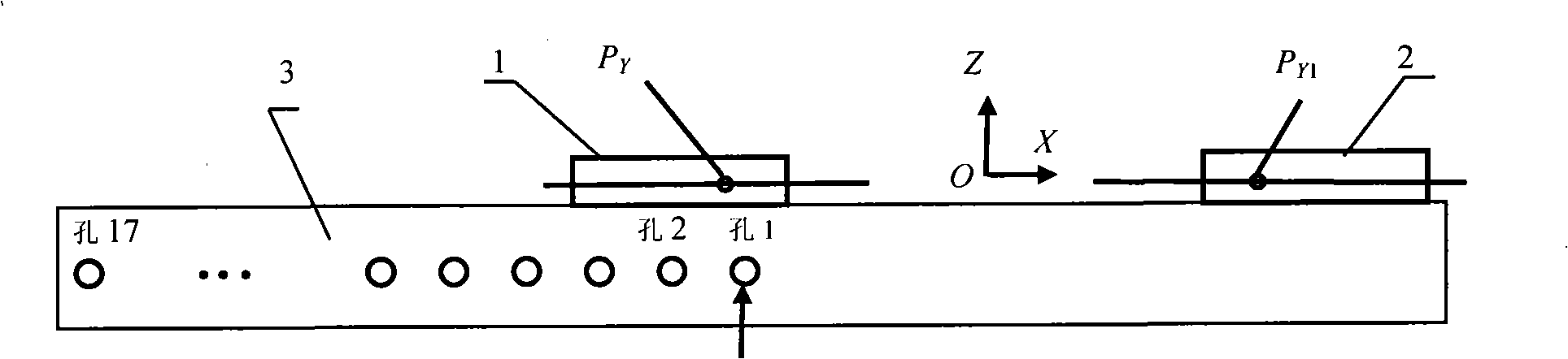
[0077] As shown in the accompanying drawings, a method for designing the loading trajectory of aircraft skin longitudinal stretching shape and NC code generation based on the numerical control longitudinal stretching machine, the specific implementation steps of the method are as follows:

[0078] Step 1: Longitudinal tensile loading trajectory design

[0079] 1. Initial hole position calculation

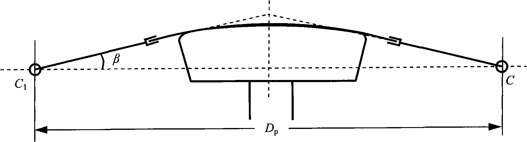
[0080] The initial hole position design is mainly based on the length of the wool and the Y rotation angle of the main shaft. figure 2 Shown is the geometric relationship of the tension state, the rotation angle of the main axis Y is β, and the fulcrum of the main axis is C 1 and C, C 1 The distance between and C is D p .

[0081] Let the wool length be L, the hole spacing be W, and the hole position be an integer n, then C 1 and the distance D between C p =D 0 +(n-1)W, when the hole position is 1, C 1 The distance between and C is D 0 . When the spindle extension is 0, t...


PUM


Abstract

The invention relates to a method for designing loading trajectory of airplane skin lengthwise stretch forming and generating numerical control codes based on ACB FEL serial numerical control lengthwise stretcher, comprising two steps: a first step: (1) designing the loading trajectory of lengthwise stretch forming and computing initial hole site; (2) initializing clamping and prestretching; (3) computing deflection angle; (4) computing jaw; and (5) searching for the excursion of the reference point of a mediate subsidiary clamp; and a second step: (1) inverse solving mechanism position and analyzing mechanism; and (2) movement evaluating. The method designs space motion location of the mediate subsidiary clamp, converts the loading trajectory into the numerical control of a device by the inverse solution, and computes the other space attitude parameter of each clamp according to the geometric characteristics of components, thereby, improving design efficiency and accuracy of stretch forming technological parameter. Optimally compared with the traditional method, the invention can obtain optimal produce technological process program, and realize scientific, numeralization and controllability of the airplane skin stretch forming. The invention has wide utility value and application prospect.

Description

[0001] The invention relates to a method for designing aircraft skin stretching trajectory, in particular to an aircraft skin longitudinal stretching trajectory design and numerical control code generation method based on ACB FEL series numerical control longitudinal stretching machine. The invention belongs to the technical field of aviation aircraft manufacturing. (two) background technology: [0002] Stretch forming (abbreviated as stretch forming) is the main manufacturing method of aircraft skin parts. The skin stretching loading trajectory refers to the three-dimensional movement path of the stretching machine clamp relative to the stretching die. Aircraft skin drawing is a complex rotary forming process, and the movement track of the clamp has a direct impact on the quality of the part. Longitudinal stretching is generally aimed at parts with double curvature or large longitudinal curvature and small transverse curvature. In recent years, domestic aviation manufacturi...

Claims


Application Information

Patent Timeline
Patent Type & Authority Applications(China)
IPC IPC(8): G05D3/00G05B19/18
Inventor 李卫东万敏阎昱韩金全
Owner BEIHANG UNIV
Why Eureka
Try Eureka