
Friction part for a frictionally acting device, and frictionally acting device having a friction part of said type

A technology of friction parts, friction action, applied in the field of friction parts for friction action devices and friction action devices with said type of friction parts, capable of solving friction lining damage, clutch difficulty, groove pattern reduction to such An obvious degree or other problems are eliminated, achieving the effect of simplification of assembly

Inactive Publication Date: 2009-08-26
BORGWARNER INC
View PDF3 Cites 16 Cited by
  • Summary
  • Abstract
  • Description
  • Claims
  • Application Information

AI Technical Summary

Problems solved by technology

Furthermore, the known groove patterns do not ensure satisfactory cooling of the friction lining or the friction surface by the oil flowing through these grooves
In addition, the high pressure of the oil may cause the friction lining to be damaged, especially if the friction lining is a paper friction lining applied to the friction lining
Another disadvantage of the known friction parts is that the so-called drag moment is not reduced to such a significant extent or eliminated by the known groove pattern
It should also be mentioned that the installation of the known discs into a clutch must be done with special care, since the arrangement of the grooves must correspond to the direction of rotation, and this makes producing a clutch consisting of these known discs much more difficult. difficulty

Method used


Image

  • Friction part for a frictionally acting device, and frictionally acting device having a friction part of said type
  • Friction part for a frictionally acting device, and frictionally acting device having a friction part of said type
  • Friction part for a frictionally acting device, and frictionally acting device having a friction part of said type

Examples


Embodiment Construction

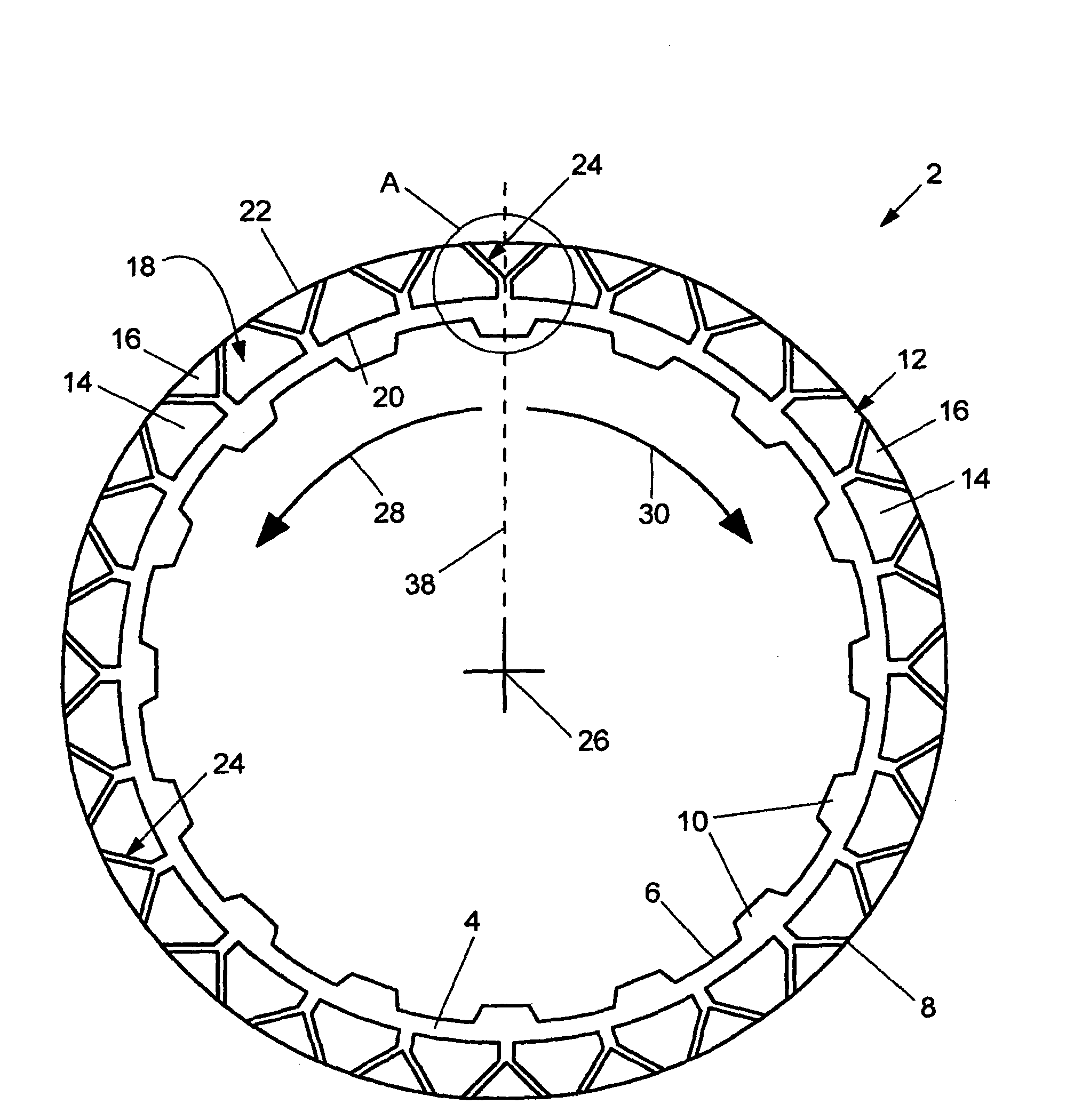
[0050] figure 1 A first embodiment of a friction component 2 for a friction device according to the invention is shown. The shown friction component 2 is embodied in the case of the variant as a plate for a multi-plate clutch and initially has a lining carrier 4 . The lining carrier 4 is embodied as an annular steel disk and comprises an inner edge 6 and an outer edge 8 . The inner rim 6 is provided with radially inwardly protruding teeth 10 formed in one piece with the disk of the ring and spaced from each other in the circumferential direction. Via these teeth 10 it is possible to connect the disc (which is therefore a so-called inner plate) rotationally and fixedly to a shaft of the clutch. However, it should be pointed out that the friction part 2 according to the invention could also be an outer plate, wherein the teeth would then be arranged on the outer edge 8 .

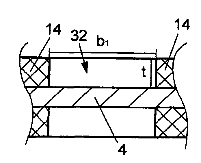
[0051] In each case, a friction lining 12 is arranged on the lining carrier 4 ( Figure 3 to Figure 5 )...


PUM


Abstract

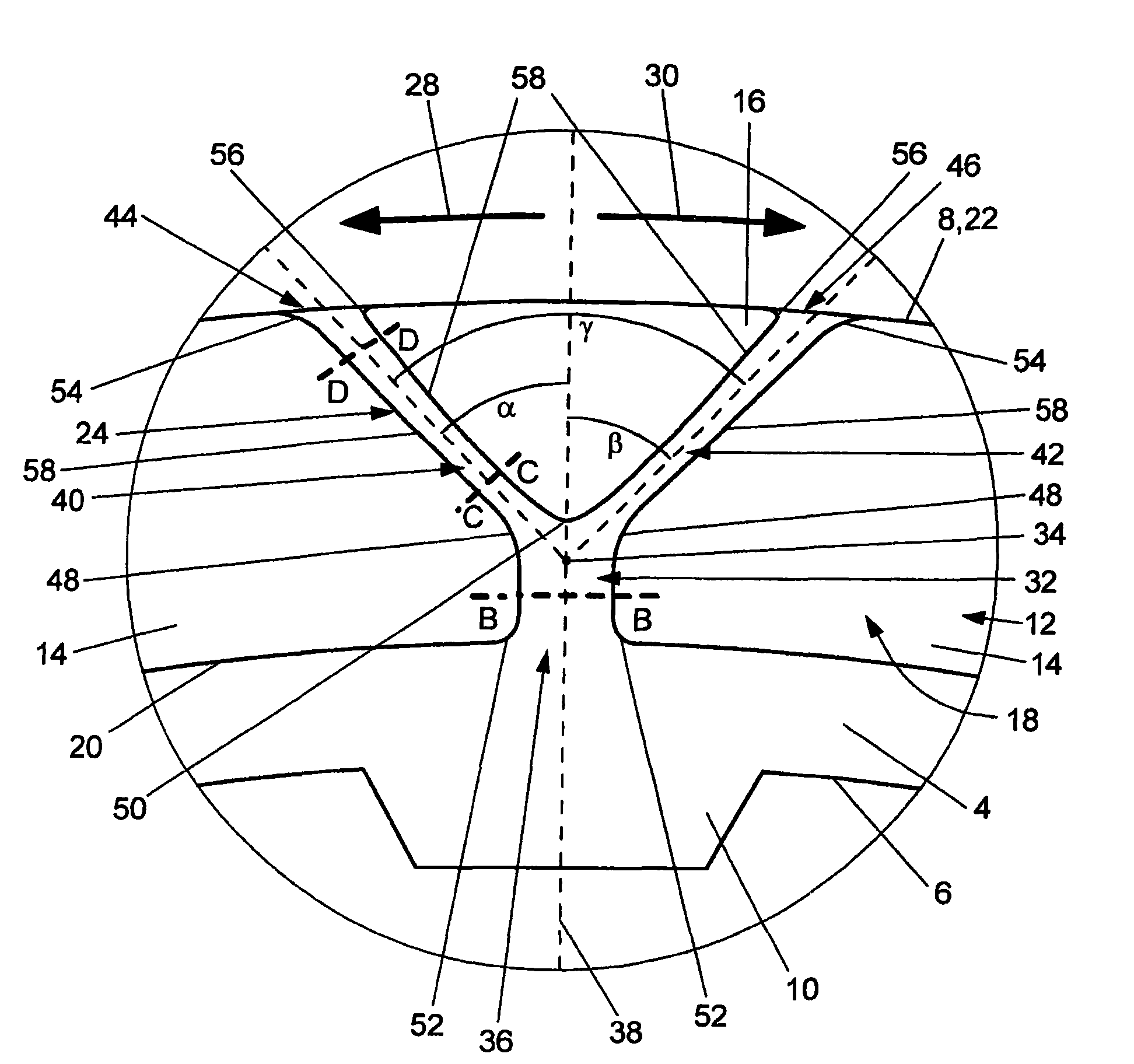
The present invention relates to a friction part (2) for a frictionally acting device, having an annular friction face (18) which has an inner edge (20) and an outer edge (22), wherein at least one set of grooves (24) is provided in the friction face (18), which set of grooves (24) has a first groove (32) which extends from the inner edge (20) or the outer edge (22) to a branching point (34) between the inner edge (20) and the outer edge (22), and a second and third groove (40, 42) which extend in each case from the branching point (34) to the other edge (22, 20). According to the invention, the second groove (40) is inclined in the one peripheral direction (28) and the third groove (42) is inclined in the other peripheral direction (30) of the friction face (18) with respect to a radial line (38) through the branching point (34). The present invention also describes a frictionally acting device having a friction part (2) of said type.

Description

technical field [0001] The invention relates to a friction element for a friction action device, the friction element having an annular friction surface having an inner edge and an outer edge, at least one set of grooves being provided in the friction surface, the The set of grooves has a first groove and a second groove and a third groove, the first groove extending from the inner edge or the outer edge to a branch between the inner edge and the outer edge At this point, the second groove and the third groove extend in each case from the branch point to the other edge. The invention also relates to a clutch for a motor vehicle having friction elements of the type described. Background technique [0002] The prior art discloses a variety of friction parts for friction action devices, such as plates for multi-plate clutches or multi-plate brakes or synchronizing rings for synchronization devices, wherein the friction part has a friction surface, in A plurality of grooves fo...

Claims


Application Information

Patent Timeline
Patent Type & Authority Applications(China)
IPC IPC(8): F16D13/64F16D13/72
CPCF16D2069/004F16D13/72F16D13/648F16D13/64
Inventor E·L·G·法布里修斯S·康瑞诺
Owner BORGWARNER INC
Learn More