Heat pump clothes-drying dehumidifying integrated machine

An all-in-one machine and clothes drying technology, which can be used in household clothes dryers, heat pumps, refrigerators, etc., to solve problems such as ignition, single function, and increased humidity, and achieve the effect of high efficiency and multiple functions.

Inactive Publication Date: 2009-09-02
梁仁建
View PDF0 Cites 31 Cited by
  • Summary
  • Abstract
  • Description
  • Claims
  • Application Information

AI Technical Summary

Problems solved by technology

However, the disadvantages of electric clothes dryers are also obvious: first, it consumes a lot of energy, because the heat generated by electric energy heats the air, and after drying the clothes, it is directly discharged, and a large amount of heat in the hot air is not reused; second, The hot and humid air generated by the electric heating dryer is directly discharged indoors, causing the indoor humidity to increase; the third is that the electric heating dryer raises the temperature of the air through an electric heater to reduce its relative humidity (for example, the temperature of the air is 25°C , the relative humidity is 80%, when heated to 60°C, the relative humidity of the air drops to 13%), the temperature of the heated air is high, generally above 50°C, such a high temperature will damage some clothes, and may even make Some chemical fiber clothes produce peculiar smell; fourth, the safety performance of drying clothes at high temperature is not high, and there is a possibility of fire; fifth, the function is single, and it is only used as a dry clothes
Due to the above-mentioned many unfavorable factors, electric heating dryers cannot be widely promoted in the market
The existing refrigerated dehumidifiers are not suitable for use in residential houses or hotels, but are only used in some special occasions, such as laboratories, precision instrument equipment rooms, etc.

Method used


Image

  • Heat pump clothes-drying dehumidifying integrated machine
  • Heat pump clothes-drying dehumidifying integrated machine
  • Heat pump clothes-drying dehumidifying integrated machine

Examples


Embodiment

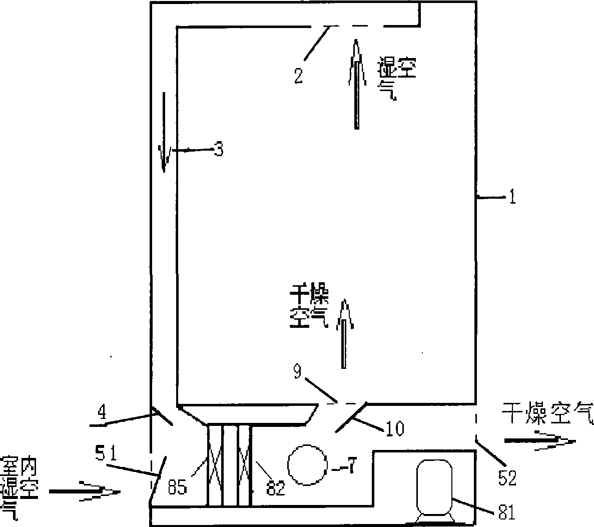
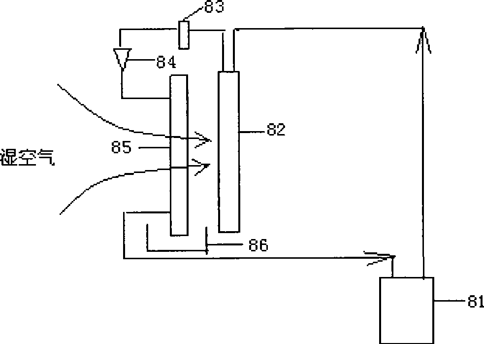
[0019] The structure of the present invention is as figure 1 As shown, it mainly includes vertical wardrobe 1, wet air outlet 2, return air duct 3, return air door 4, dehumidification inlet door 51, dehumidification outlet door 52, heat pump system, circulation fan 7, drying air outlet 9, drying Clothes air damper 10, control system, etc. Wet air outlet 2, return air duct 3, return air door 4, drying air outlet 9, and drying air damper 10 form the drying air passage, while the dehumidification inlet door 51, dehumidification outlet door 52, and drying air damper 10 are composed The dehumidification air flow channel, and the dry clothes air flow channel intersects with the dehumidification air flow channel, and a heat pump system is arranged at the intersection. The structure of the heat pump system is as figure 2 As shown, it comprises a compressor 81 connected in sequence, a condenser 82, a dry filter 83, a thermal expansion valve 84, and an evaporator 85. A water pan 86 i...


PUM


Abstract

The invention relates to a heat pump clothes-drying dehumidifying integrated machine, which is highly efficient, energy-saving and environment-friendly. The machine comprises a wardrobe, a heat pump system, a fan and a control system, wherein the control system is connected with the heat pump system and the fan respectively; the machine also comprises a clothes-drying air channel and a dehumidifying air channel; one end of the clothes-drying air channel is connected with the upper end part of the wardrobe, while the other end is connected with the lower end part of the wardrobe; the dehumidifying air channel is arranged on the lower end part of the wardrobe, and intersects with the clothes-drying air channel; and the heat pump system is arranged at the intersection of the clothes-drying air channel and the dehumidifying air channel. The machine realizes the function of multi-functions by one machine, and can dry clothes as well as dehumidify a room in wet seasons; moreover, the machine can also be used as a wardrobe while in not use; and the wet air generated when drying clothes is not directly exhausted, but circulates in the system, thereby improving the working efficiency and saving energy.

Description

technical field [0001] The invention relates to a clothes dryer and dehumidifier, in particular to a heat pump clothes dryer and dehumidifier integrated machine. Background technique [0002] In the rainy season, although the temperature is not too low, due to the high air humidity, the changed clothes often cannot be dried for more than a week. smell. In addition, in the room during the rainy season, indoor quilts and clothes will also become moldy, smelly, or even rotten due to the high humidity of the air. [0003] At present, the electrical equipment related to drying clothes and dehumidification on the market have separate functions; only electric clothes dryers are the only clothes dryers. The electric clothes dryer is easy to operate, relatively small in size, and has a relatively fast drying speed. However, the disadvantages of electric clothes dryers are also obvious: first, it consumes a lot of energy, because the heat generated by electric energy heats the air,...

Claims


Application Information

Patent Timeline
Patent Type & Authority Applications(China)
IPC IPC(8): D06F58/10D06F58/20B01D53/26F25B30/00
Inventor 梁仁建林浩
Owner 梁仁建
Why Eureka
Try Eureka