
High temperature valve

A valve, high-temperature technology, applied in the field of high-temperature valve devices, can solve the problems of difficult popularization, short service life, hidden safety hazards, etc., and achieve the effects of reducing production costs, improving service life, and reducing cracks

Inactive Publication Date: 2009-09-02
WUCHANG SHIPYARD
View PDF0 Cites 6 Cited by
  • Summary
  • Abstract
  • Description
  • Claims
  • Application Information

AI Technical Summary

Problems solved by technology

Water-cooled high-temperature valves require a large amount of softened cooling water. This kind of valve has great problems in areas where water is scarce, and most of the coal coking industry is in water-scarce areas. Hidden danger, once the water jacket leaks, it will cause an explosion accident
No cooling water high-temperature valve, the middle is heat-resistant steel outer double-sided refractory material, because there is no cooling, long-term high temperature 1300 ℃, heat-resistant steel can not withstand, so the service life is very short, the general service life is only 3 months to one year , and the temperature is greater than 1300 ℃ can not be used
At present, the existing foreign high-temperature valves that can withstand 1300°C adopt water-cooling mode, but the price is expensive, and there are high requirements for cooling water medium during use, so it is difficult to popularize and adopt them in large quantities.

Method used


Image

  • High temperature valve
  • High temperature valve

Examples


Embodiment Construction

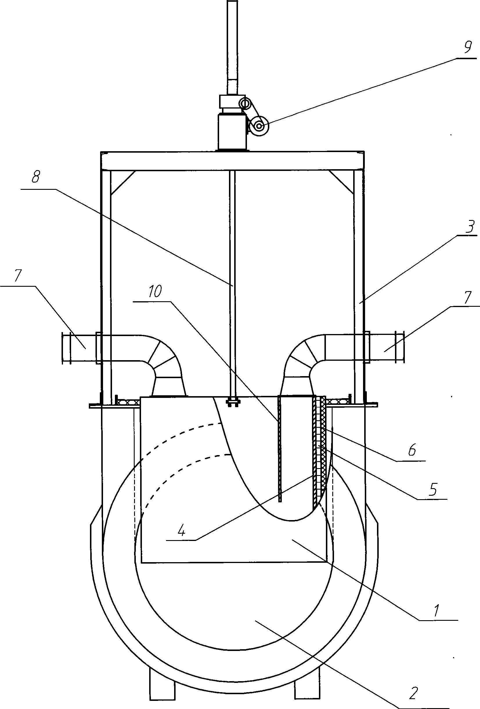
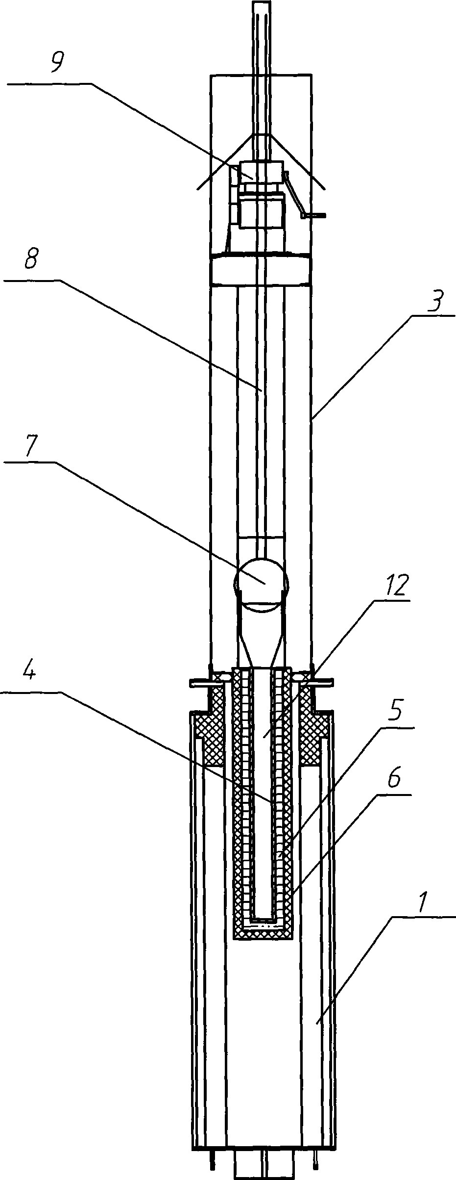
[0012] Such as figure 1 As shown, the valve plate 2 on the valve body 1 is movably connected to the lower part of the door frame 3, and the hoist 9 is installed on the door frame 3, and connected to the valve plate 2 through a screw rod 8, which is used to adjust the valve plate 2 to the valve body 1. opening and closing. The valve plate 2 is a cavity structure, and the left and right air inlet pipes 7, 17 are respectively installed on the top of the valve plate 2 through the air inlets 13, 23 on the valve plate 2 and connected to the cavity 12. The other ends of the air inlet pipes 7, 17 Connect the external fan, and the external fan blows cold air into the cavity 12 through the air inlet pipes 7 and 17; figure 1 The middle curve A is the partial cross-sectional line of the valve plate 2. As shown in this partial cross-sectional view, the cold air sent by the air inlet pipe 7 enters the inner cavity of the valve plate 2, and is guided by the inner cavity wall 4 and the air d...


PUM


Abstract

The invention relates to the filed of high temperature valve devices, and provides a high temperature valve, which comprises a valve body and a valve plate, wherein the valve plate has a cavity structure; the cavity structure comprises an air inlet and an air outlet which are positioned on the top of a cavity; and the air inlet is connected with an air inlet pipe. The valve plate adopts a heat-resistant steel cavity structure and hollow air-cooled heat radiation, an inner cavity is externally stuck with a high-temperature heat insulating material, and an outer layer of the high-temperature heat insulating material is provided with a high-temperature refractory material to further reduce the temperature tolerated by heat-resistant steel and prolong the service life of the heat-resistant steel. Simultaneously, compared with the prior water-cooled high temperature valve, the high temperature valve saves water resources and greatly reduces the production cost. In addition, the inner cavity of the valve plate is made of a heat-resistant steel material and compared with the prior heat-resistant steel material, the high temperature valve saves the production cost, reduces cracking of the valve plate refractory material caused by expansion of the heat-resistant steel, and solves the problem of thermal deformation.

Description

technical field [0001] The invention relates to the field of high temperature valve devices. Background technique [0002] As an important supporting equipment for production lines such as coke ovens, high-temperature valves usually include water-cooled high-temperature valves and high-temperature valves without cooling water. Water-cooled high-temperature valves require a large amount of softened cooling water. This kind of valve has great problems in areas where water is scarce, and most of the coal coking industry is in water-scarce areas. Hidden danger, once the water jacket leaks, it will cause an explosion accident. No cooling water high-temperature valve, the middle is heat-resistant steel outer double-sided refractory material, because there is no cooling, long-term high temperature 1300 ℃, heat-resistant steel can not withstand, so the service life is very short, the general service life is only 3 months to one year , and the temperature is greater than 1300 ℃ can...

Claims


Application Information

Patent Timeline
Patent Type & Authority Applications(China)
IPC IPC(8): F16K3/30F16K3/02F16K49/00F16K27/04
Inventor 陈云斌邹宜陵李翔潘中怀陈绪志
Owner WUCHANG SHIPYARD
Learn More