Liquid crystal box thinning method and liquid crystal box thinning equipment

A liquid crystal cell and equipment technology, applied in optics, non-electric variable control, instruments, etc., can solve the problems of large differences in the overall thickness of the liquid crystal cell, incomplete cutting, fragmentation, etc., achieve good optical characteristics, and eliminate the effect of the overall thickness difference

Active Publication Date: 2011-10-19
KUSN INFOVISION OPTOELECTRONICS
View PDF0 Cites 0 Cited by
  • Summary
  • Abstract
  • Description
  • Claims
  • Application Information

AI Technical Summary

Problems solved by technology

Therefore, there is also a certain thickness difference between different first substrates
Therefore, although the cell pitch of different liquid crystal cells after assembly, that is, the distance between the first substrate and the second substrate, is uniform, the overall thickness of the liquid crystal cells varies greatly, and the existing thinning technology cannot eliminate the difference. There is a thickness difference in the overall thickness of the liquid crystal cells, and the overall thickness difference of different liquid crystal cells will have different effects on the optical characteristics of the liquid crystal display substrate, and in the subsequent cutting and splitting process, there may be a large difference in the overall thickness of the liquid crystal cell There are problems such as burrs on the edge of the first substrate or the second substrate when the cutting is incomplete or split on the first substrate or the second substrate; and the fragmentation occurs on the first substrate or the second substrate with a small difference in the overall thickness of the liquid crystal cell. question

Method used


Image

  • Liquid crystal box thinning method and liquid crystal box thinning equipment
  • Liquid crystal box thinning method and liquid crystal box thinning equipment
  • Liquid crystal box thinning method and liquid crystal box thinning equipment

Examples


Embodiment Construction

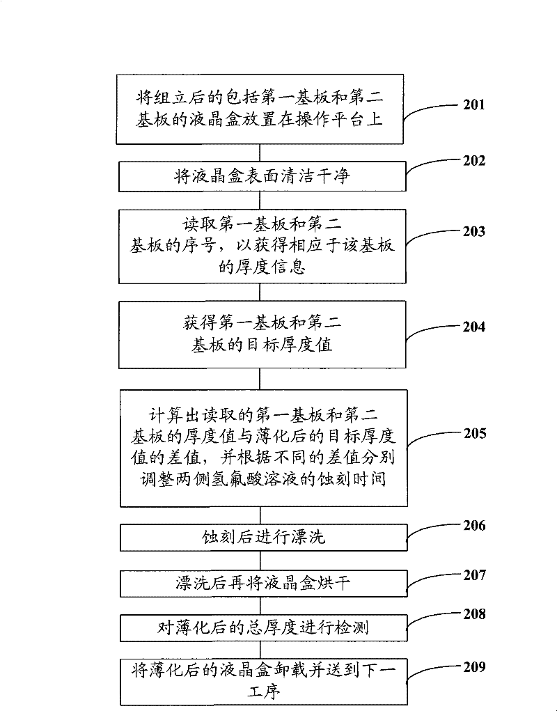
[0022] figure 2 It is a schematic process flow diagram of a liquid crystal cell thinning method according to an embodiment of the present invention.

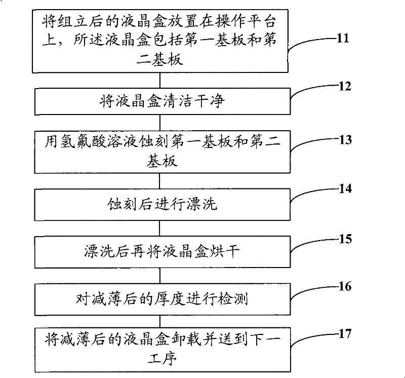
[0023] Step 201, placing the assembled liquid crystal cell including the first substrate and the second substrate on the operation platform.

[0024] Wherein, the first substrate may be a color filter substrate, the second substrate may be a thin film transistor substrate, and the first substrate and the second substrate may be purchased from different suppliers, and may be of different batches. manufactured products. The specifications of the first substrate and the second substrate can be all specifications that can be supplied by the substrate supplier, specifically, they can be, for example, 0.5 mm, 0.6 mm, 0.7 mm, 0.8 mm, and 0.9 mm. The first substrate and the second substrate are in the same specification, and their thickness parameters may be within a thickness error range of 10%. Taking a substrate with a thickness ...


PUM

PropertyMeasurementUnit
thicknessaaaaaaaaaa
thicknessaaaaaaaaaa

Abstract

The invention relates to a liquid crystal box thinning method and liquid crystal box thinning equipment. The liquid crystal box thinning method comprises the following steps: providing a liquid crystaThe invention relates to a liquid crystal box thinning method and liquid crystal box thinning equipment. The liquid crystal box thinning method comprises the following steps: providing a liquid crystal box comprising a first baseplate and a second baseplate; respectively obtaining the thinning thicknesses of the first baseplate and the second baseplate; thinning the liquid crystal box and respectil box comprising a first baseplate and a second baseplate; respectively obtaining the thinning thicknesses of the first baseplate and the second baseplate; thinning the liquid crystal box and respectively controlling the thinning conditions of the first baseplate and the second baseplate according to the thicknesses of the first baseplate and the second baseplate. The liquid crystal box thinning mvely controlling the thinning conditions of the first baseplate and the second baseplate according to the thicknesses of the first baseplate and the second baseplate. The liquid crystal box thinning method accurately controls the thinning thicknesses of the first baseplate and the second baseplate, thereby achieving the purpose of accurate thinning.ethod accurately controls the thinning thicknesses of the first baseplate and the second baseplate, thereby achieving the purpose of accurate thinning.

Description

technical field [0001] The invention relates to the technical field of liquid crystal display manufacture, in particular to a liquid crystal cell thinning method and liquid crystal cell thinning equipment. Background technique [0002] With the wide application of liquid crystal displays, people have higher and higher requirements for liquid crystal displays. In addition to requiring high brightness, high contrast, high resolution, high color saturation and fast time response, another issue that liquid crystal displays face It is thinning, and the key component liquid crystal box in the liquid crystal display is an important factor for the thinning of the liquid crystal display. The liquid crystal cell is composed of a first substrate and a second substrate bonded together, and an optically active substance, such as liquid crystal, is arranged inside it. Since the proportion of the first substrate and the second substrate is large, and it is necessary to ensure mechanical s...

Claims


Application Information

Patent Timeline
Patent Type & Authority Patents(China)
IPC IPC(8): G02F1/1333G05D5/02
Inventor 毛联波简廷宪邱郁雯钟德镇向贤明张少楠
Owner KUSN INFOVISION OPTOELECTRONICS
Why Eureka
Try Eureka