

Method and device for plasma-assisted chemical vapour deposition on the inner wall of a hollow body
A plasma, hollow technology, applied in gaseous chemical plating, electrical components, transportation and packaging, etc., can solve problems such as problems, unsuitable for wide application, limited hollow body geometry, etc., to achieve the effect of promoting the dissociation process
- Summary
- Abstract
- Description
- Claims
- Application Information
AI Technical Summary
Problems solved by technology
Method used
Image

Examples
Embodiment Construction
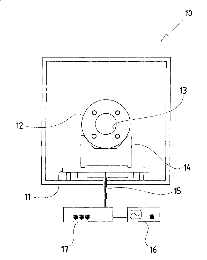
[0113] figure 1 Shown is the front cross-sectional view of the vacuum chamber 10 provided by the present invention, the radio frequency electrode 11 is arranged at the bottom of the chamber, the inner side of the hollow body is to be plated and has an opening 13, and the hollow body is arranged on the radio frequency through an assembly 14 on the electrode.
[0114] The radio frequency electrode 11 inside the vacuum chamber 10 has three lead wires 15 through which a radio frequency voltage generated by a radio frequency generator (RF generator) 16 is fed to the radio frequency electrode 11 . By means of a matching box connected between the adjustable generator 16 and the RF electrode 11, as it is called, the individual leads of the RF electrode 11 can be individually adjusted with the aid of trimmer potentiometers to produce Uniform alternating field of uniform high magnetic field strength.
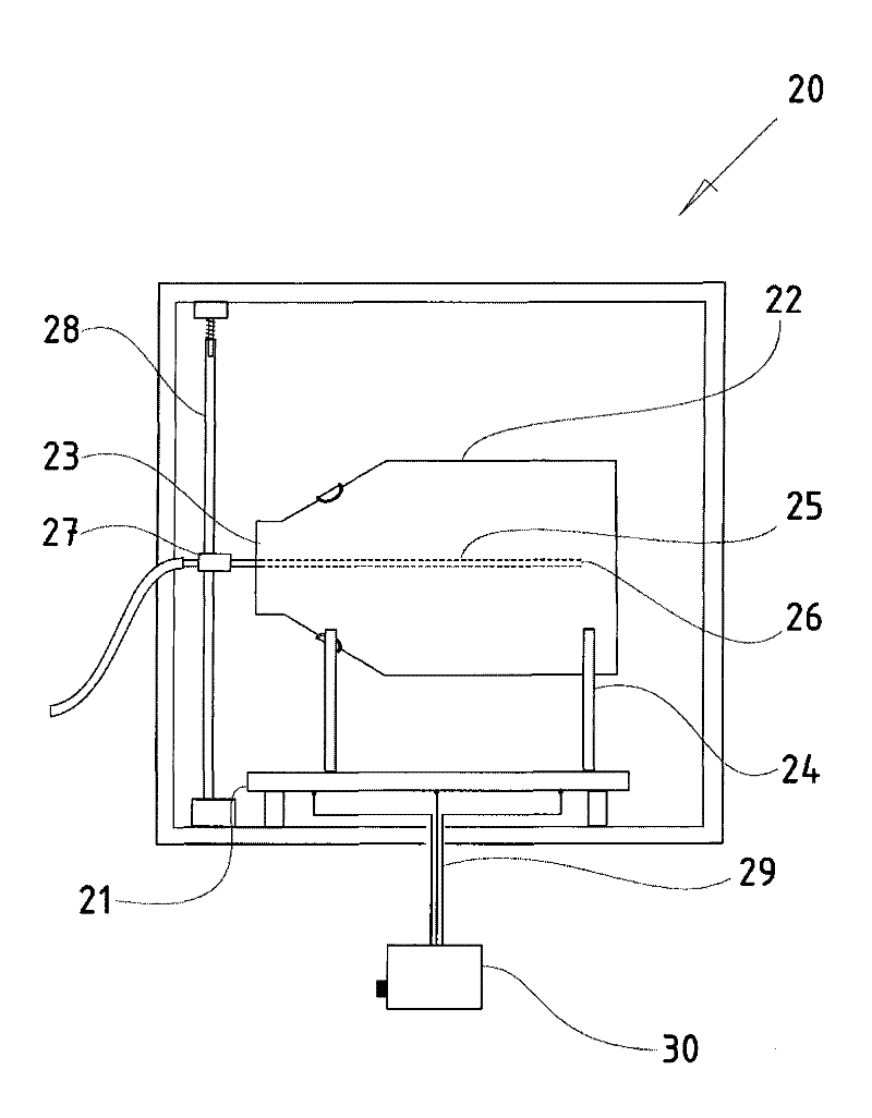
[0115] figure 2 Shown is a side sectional view of the same vacuum chamber 20, wit...
PUM
 Abstract
Description
Claims
Application Information