
Refrigerating arrangement comprising a hot connection element and a cold connection element and a heat exchanger tube connected to the connection elements

A refrigeration system and thermal connection technology, applied in electrical components, household refrigeration devices, coolers, etc., can solve problems such as the inability to limit the loss of circulating refrigerant, and achieve the effect of reducing heat transfer capacity

Inactive Publication Date: 2009-09-02
SIEMENS AG
View PDF6 Cites 18 Cited by
  • Summary
  • Abstract
  • Description
  • Claims
  • Application Information

AI Technical Summary

Problems solved by technology

In this case, although the losses caused by the solid heat transfer system can be limited, the losses caused by the circulating refrigerant cannot be limited

Method used


Image

  • Refrigerating arrangement comprising a hot connection element and a cold connection element and a heat exchanger tube connected to the connection elements
  • Refrigerating arrangement comprising a hot connection element and a cold connection element and a heat exchanger tube connected to the connection elements
  • Refrigerating arrangement comprising a hot connection element and a cold connection element and a heat exchanger tube connected to the connection elements

Examples


Embodiment Construction

[0036] The same components are denoted by the same reference symbols in the various drawings. Components not specified in detail belong to the general prior art.

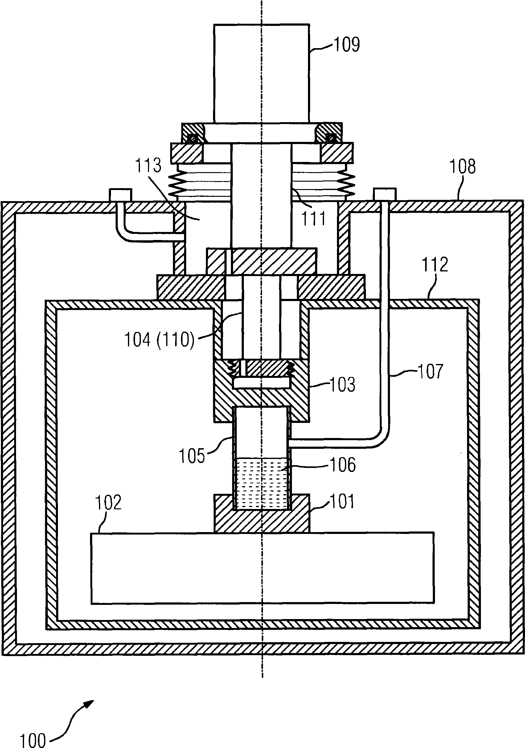
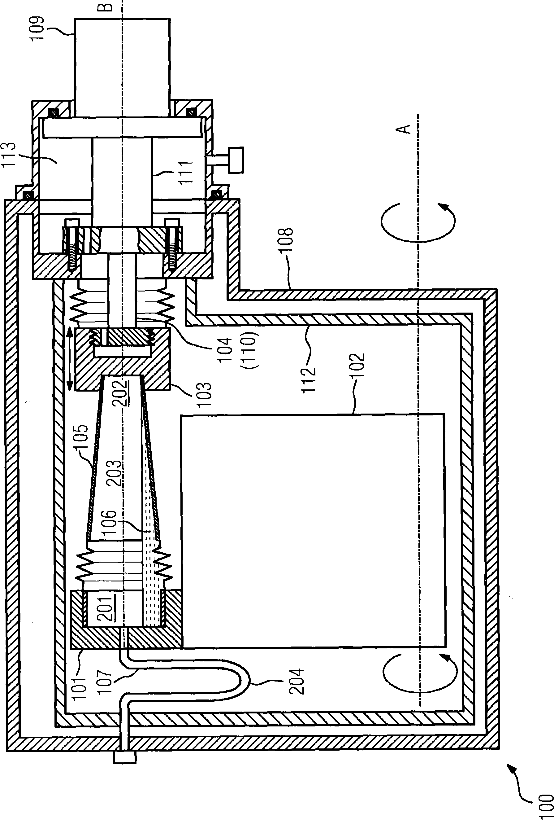
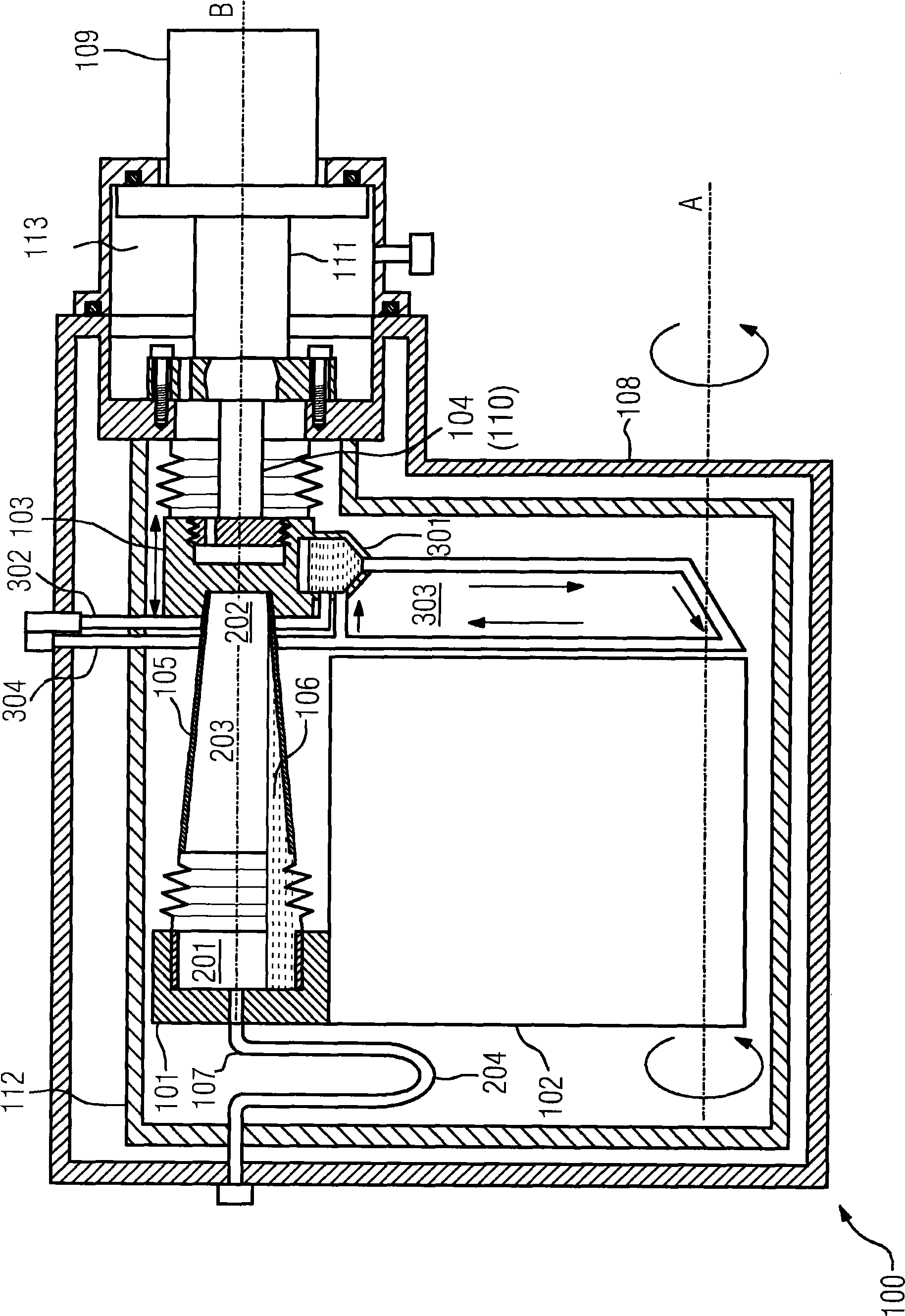
[0037] figure 1 Shown is a schematic structural diagram of a refrigeration system 100 in one embodiment. The part 102 of the device to be cooled is located in a cryostat 108 . By way of example, the component to be cooled 102 of the device may be a magnet winding of a superconducting magnet or another component of superconducting technology. In order to improve the heat insulation effect, a heat insulation board 112 is installed in the cryostat 108 . Refrigeration energy for the components to be cooled 102 of the device is provided by a refrigerator 109, such as a cold head or a Stirling refrigerator. Cold heads which operate according to the Gifford-McMahon principle can preferably be used. According to this embodiment, such a two-stage refrigerator can be thermally connected via its first stage 111 to a heat ...


PUM


Abstract

The invention relates to a refrigerating arrangement (100) comprising a hot connection element and a cold connection element (101, 103) and a heat exchanger tube arranged between said connection elements (101, 103). The heat exchanger tube (105) is to be at least partially filled with a liquid (106) that can be circulated in the heat exchanger tube (105) by a thermosiphon effect. The parts (102) to be cooled of a device, especially used in supraconductivity technology, are connected to the hot connection element (101), and a heat sink (104) is connected to the cold connection element (103). In order to thermally separate the connection elements (101, 103), the liquid (106) can be pumped out by means of a pipeline (107) connected to the inside of the heat exchanger tube (105).

Description

technical field [0001] The present invention relates to a refrigeration system, which has [0002] - at least one thermal connection element thermally connected to a part of the device to be cooled, [0003] - at least one cold connection element, thermally connected to the cold source, [0004] - at least one heat pipe made of a material with poor thermal conductivity, connected at a first end to said hot connection element and at a second end to said cold connection element, the inner cavity of which is at least partially filled with a thermosyphon effect. circulating liquid. Background technique [0005] A refrigeration system having the above-mentioned features is disclosed, for example, from DE 102 11 568 B4. [0006] Cooling systems, for example for superconducting magnets, usually use the so-called bath cooling method. This bath cooling can use a liquid refrigerant such as helium at a temperature of typically 4.2K. The superconducting electromagnetic coil system ...

Claims


Application Information

Patent Timeline
Patent Type & Authority Applications(China)
IPC IPC(8): F25D19/00F25D16/00
CPCF25D19/006H01F6/04F28D15/02F25D16/00F28F2013/005F25D19/00
Inventor 马赖南·彼得·奥姆彼得·范·哈塞尔特
Owner SIEMENS AG
Learn More