Air finishing machine

An air conditioning and rack technology, which is used in dryers, progressive dryers, textile materials processing, etc., can solve the problems of wasting fabrics, manpower, and raw materials, and achieves uniform smoothness and reduced The effect of labor cost and production cost reduction

Inactive Publication Date: 2011-08-10
王绍福
View PDF0 Cites 1 Cited by
  • Summary
  • Abstract
  • Description
  • Claims
  • Application Information

AI Technical Summary

Problems solved by technology

[0003] 1. There are many processes in the fabric finishing process, which requires the cooperation of multiple workers (usually about 10 people) to complete, and the waste of manpower is serious;
[0004] 2. A large amount of waste water will be generated during the finishing process of fabrics, which not only pollutes the environment, but also wastes raw materials seriously;
[0005] 3. The degree of automation in the finishing process of the fabric is low, the labor intensity of the workers is high, and the production cost of the product is correspondingly high;
[0006] 4. During the finishing process, the fabric fabric must be cut into small pieces, which seriously wastes the fabric fabric, and is prone to produce a large number of folds, dead wrinkles, sand roads and other defective products

Method used


Image

  • Air finishing machine
  • Air finishing machine
  • Air finishing machine

Examples


Embodiment 1

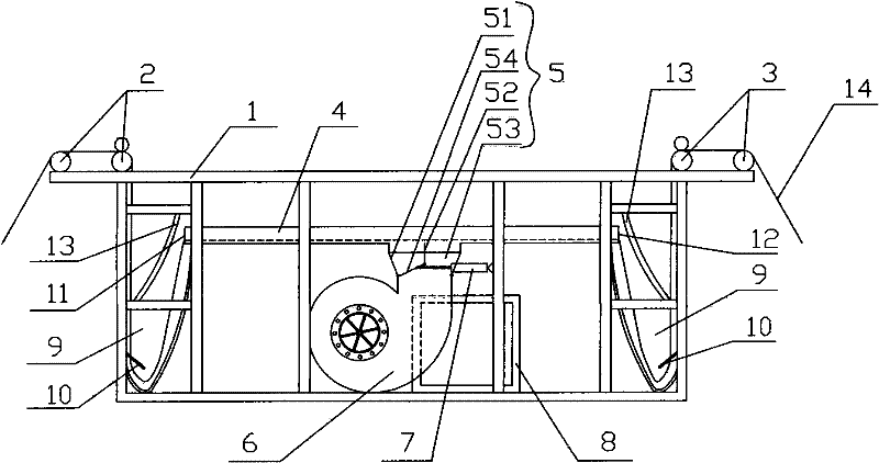
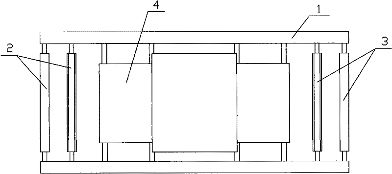
[0021] Embodiment 1: refer to figure 1 , figure 2 As shown, it is a preferred embodiment of the present invention, a kind of air finishing machine, comprising a frame 1, positioned at the top of the frame 1 and cloth feeding rollers 2 and cloth discharging rollers 3 are respectively installed on the left and right sides of the frame. An air duct 4 for fabric 14 to pass is installed in the frame 1, and a tuyere box 5 is communicated in the middle of the air duct 4, and the air inlet of the tuyere box 5 communicates with the air outlet of the blower 6, and the tuyere box 5 includes a box body 51, a partition 52 is arranged in the box body 51, and two air inlet passages 53 are formed in the box body 51 through the partition board 52, and one end of the partition board 52 is hinged to be used for closing one of the air inlet passages. 53 of the movable wind plate 54, the movable wind plate 54 is connected with the cylinder 7, the work of the cylinder 7 can swing the movable wind...

Embodiment 2

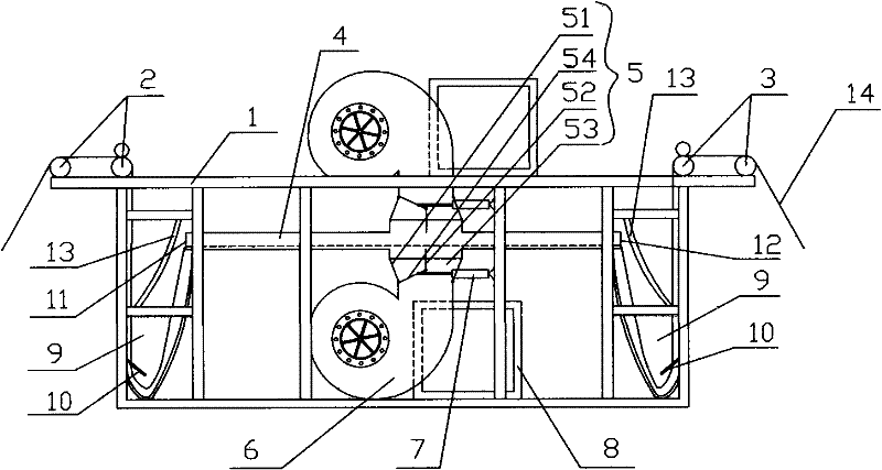
[0023] Embodiment 2: refer to image 3 As shown, it is another preferred embodiment of the present invention. The difference between this embodiment and Embodiment 1 is that there is a tuyere box 5 in the middle of the air duct 4 and connected to the upper and lower sides, each The air nozzle box 5 is connected with blower 6 and cylinder 7 independently, and on the air inlet that is positioned at blower 6 on frame 1, also all is equipped with cooling box 8. When in use, the wind force produced by the upper and lower blowers 6 can act on the fabric 14 in the air duct 4 simultaneously according to the requirements of the fabric 14, so that the fabric 14 moves back and forth faster and more efficiently. The rest of this embodiment is the same as that of Embodiment 1, and will not be repeated here.


PUM


Abstract

The invention discloses an air finishing machine, comprising a frame. The left and right sides of the frame are respectively provided with a draw-in roller and a draw-out roller, the frame is internally provided with an air duct for fabrics to pass through, the air duct is communicated with an blast nozzle case, an air inlet of the blast nozzle case is communicated with an air outlet of a blower,the blast nozzle case is provided with a cylinder for controlling the wind direction thereof, a radiator case is disposed on the frame and just on the air inlet of the blower. After adopting the structure, the air finishing machine has reasonable structure, simple operation and low cost, can automatically finish fabrics and facilitates the finished fabric to have superior elasticity, softness andsmoothness; meanwhile, the air finishing machine can facilitate the fabric to have neatness and attractive appearance,and can prevent numerous defective fabrics with wrinkles, dead wrinkles, sand tracts and the like.

Description

technical field [0001] The invention discloses an air finishing machine, which belongs to the technical field of equipment for the post-finishing process of textile products. Background technique [0002] At present, in order to make the woven fabric have elasticity and softness, it is generally necessary to carry out the post-finishing process after the fabric is woven, that is, the fabric is first packed in the yarn washing bag, and then the yarn washing bag with the fabric is placed Put it into the yarn washing tank to add material (soft oil or silicone oil) to make it soft, and run it. After the operation is completed, put water to clean it, and then the worker pulls the yarn washing bag out of the yarn washing tank. Put them into the dehydrator and rolling oven for dehydration and drying in turn. After drying, each worker will arrange the fabric. After the finishing process, although the woven fabric can have certain elasticity and softness, there are also some defects...

Claims


Application Information

Patent Timeline
Patent Type & Authority Patents(China)
IPC IPC(8): D06B3/28D06B23/20D06B23/00F26B13/02F26B3/10
CPCD06C19/00
Inventor 王绍福
Owner 王绍福
Why Eureka
Try Eureka